Are you planning for job change? then first you must start preparing for the interview.
We prepared an article for DCS and Field Instruments Questions and Answers which might helpful for your preparation. Share your feedback on the article. All the best.
Field Instruments Questions and Answers

Control Room Questions and Answers
What is DCS & PLC?
Distributed control system(DCS) and Programmable logic controller. These are the control systems which handles fields I/Os.
Basic difference between DCS & PLC is
1) DCS handles more nos of I/Os rather than PLC.
2) PLC is faster system than DCS. 3) DCS can handles handsome quantity of I/Os so that can be used for total plant automation. Where as PLC has own limitations so it generally used for small but for important(Safety point of view) units, like boiler automations, Make-up compressor automations Etc.
4) In the above mentioned case the these PLC’s can be get connected with the DCS with the help of soft link. Generally this is used to make alert to both the operator.
5) As I heard the PLC used to handle the DI/DO signals so it can take fast actions. Some of the time it is used to handle few nos of AI/AO.
6) DCS & PLC’s speed depends on the scan rate of I/Os.
7) For both the system Marshalling panels, Consoles and other faculties of Ethernet Etc can be used according to the need.
8) According to the Cause and effects diagrams the System programmer assigns the control action block into the system, we can call them as memory assigning.
While making Datasheets which things are to be considered?
Basically it depends on the instrument item for which you are preparing the datasheet.
As an Example. Temperature Element. We have collect following information to prepare D/s.
What is potential free contact? What is the significance and application of this contact?
Contacts having not potential. E.g. Relay contacts/ field switches contacts. They are used in logic circuits.
A potential free contact is usually wired into an electrical circuit.
However it must be ensured that the contact ratings are suitable for the service in which it is used.
In split range control, whether the signal is splitted through I/P convertor or the convertor itself?
This can be typically achieved by two ways:
By connecting o/p of one I/P converter to two positioners adjusted suitably for split range operation of control valves.
Taking two Analog Outputs (AO) from DCS. Split range to be defined in DCS. Both I/P converters and positioners to be calibrated with input as 4to20 ma dc and 3to15 psi respectively.
When do we use SOV of rating 110vac and 110vdc?
Primarily depends upon the availability of reliable power supply source.
How is cold junction compensation in thermocouple carried?
This is typically performed in modern programmable instruments by means of measuring actual reference junction temperature using a temperature sensor mounted close to the ref. junction and compensating for the same using appropriate look-up table stored within the instrument’s memory.
In which applications do we use 4 wire RTD?
Three wire is a better alternative. Primary objective of 3-wire and 4-wire arrangements is to eliminate effects of lead resistance on temp. measurement.
What is the sensor used in coriollis mass flow meter to measure density?
Density is measured here by measuring the resonant frequency of a vibrating U-tube.
What if thermocouple wire is opened in the field? What signal goes to DCS?
In most modern instruments the signal may be programmed to go to either maximum or minimum depending upon end user’s requirement.
if the power supply connections to a two-wire transmitter get interchanged? What signal will go to DCS?
Usually there is a blocking diode to protect the transmitter against supply reversal and almost zero current signal should be transmitted.
What are the possible reasons for the failure of barrier? !?!
Fuse blowing sometimes. Power circuits are most likely to fail.
How can we say that the given RTD or Thermocouple is correct?
We can only measure sensor output (resistance / maillots ) accurately and look-up corresponding temperature in reference tables.
The accuracy depends upon quality / condition of the sensor. Degraded sensors may not give accurate readings and must be replaced.
To test a sensor, the sensor response may be tested using a high quality temperature calibrator and compared with reference tables.
In some cases we have to select the cam position in a control valve for different application? How do we select that?
Refer to instruction manual for the positioner / control valve.
The cams are often marked with limited amount of information, which may help an experienced person.
What is the difference between a protocol and a field bus?
A protocol defines a standard method for communications.
A fieldbus is a multidropping arrangement where multiple instruments communicate with special interface hardware using the same pair of wires and in most of the cases draw power from the same pair of wires.
What happens if transmitter wires get shorted?
The barrier if installed limits electrical energy flowing into hazardous area. If there is no barrier, typically a fuse in the power distribution system will blow.
What will happen if thermocouple wires get shorted?
A cold junction compensated instrument will typically indicate temperature of the location where the T/C wires are shorted.
Why do we require loop-terminating resistor in any digital communication loop?
A minimum loop resistance is required so that modulated current signal produces a modulated voltage signal, which may be detected by the receiving equipment.
What is adapter flange?
It is a transmitter part for allowing process connection to pipe/tube.
How to calculate the safe distance between cables to avoid electromagnetic interference of each other ?
The design engineers / equipment manufacturers follow/publish certain guidelines w.r.t. different types of cables and the voltages/currents and types of signals carried by them.
How Control loop should be tuned in process loop?
You may use Ziegler-Nichol’s method ( open loop / closed loop ) or special tuning software tools.
What is the significance of single ended & differential ended input for PLC? Application wise comparison of these two types of inputs?
Differential inputs provide better common mode rejection and signal-to-noise ratio.
What is Ground Loop? Preventive steps to avoid ground loop?
When ground wiring is not done properly, grounding of various points is not effective and potential differences exist between them resulting in currents flowing between them.
This leads to measurement errors and is not desirable. It can be eliminated by proper ground wiring.
In a globe type control valve, what is the importance of flow direction (top to bottom or bottom to top)?
Control valves must be installed as per direction marking provided by the manufacturers or instruction manuals. Though people tend to generalize, this is often misleading.
What is ATEX directives / FM Approval / CSA approved / CE certified ? What is the importance of individual certification? Are all these certification required for each instruments? Which certification do we prefer?
ATEX/FM/CSA certifications generally refer to certification for suitability of instruments for use in hazardous area when installed in accordance with recommended guidelines.
Any certification, which is locally acceptable as per statutory requirements, may be used. We typically accept American/European/Indian certifications/approvals in India.
Advantages of tachometer as speed measuring device compared to inductive type proximity switches?
Some tachometers provide analog output with almost instantaneous response time.
They are highly suitable for speed control in some applications.
Application wise advantages of Inductive type proximity switches over capacitive type switches?
Inductive proximity switches are better suited for detection of conducting metal objects and are easily tested for proper operation.
Capacitive switches are typically used for detecting non-conductive materials.
What is cable tray? Its type? Its size? Its support?
Cable tray is nothing but the way or media through which we lay the field cables in plant.
There are two basic types
- Ladder type(made in Rungs type construction)
- Perforated Type(Solid sheath consist of Holes for ventilation).
Basically discussing about tray support than we could say it depends on the site conditions. Only care has to be taken considering adequate space for laying cable, considering their bends.Etc.
How to decide cable tray size?
According to the no. of cable occupancy in the cable tray and available tray size we have to choose it. they are available in foll. types 80,150,300,450,600 & 900.
What is meant by instrument location & JB location?
This consist of Instrument location considering the piping drawing given from Piping dept. We identifies the locations of the instrument in the equipment layouts and put the bubbles and elevation and JB nos for the location.
Same way depending upon the accessibility we decide the location of JB and marking of it into the instrument location plan is JB location. There is no need to make a different drawing for this.
While locating Instrument & JB which things we have to consider?
Transmitter : Tube routing, maintenance area, man approach, Valve : Hand wheel operations, Maintenance area, Etc.
Loop power indicators : Man approach Illumination from Electrical if instrument is not going to provide.
What is the use for cable entry in control room? (sleeves & MCT)
In the process plant Control room built considering the non-hazardous area.
So in case if fire/Explosion takes place in the plant than that has to be restricted from entering into the control room. So MCT (Multiple cable transient) blocks are used.
They are designed to sustain the fire for a fixed time duration. That block hold the cables which are entering into the CCR.
What are Analog Input/output & Digital Input/output?
- 4-20 mA signals from instrument (transmitters) are analog input to control system.
- 4-20 mA signals to instrument (I/p & electro pneumatic positioner) are analog output from control system.
Volt free (24V) contact (NO/NC) by instruments (all type of switches, ex. Limit switch, press,temp,flow,level switch) are digital input to control system.
All powered signals (24V,48V,110V….) from system to instruments (SOV) are Digital outputs.
Types of instrument cables?
- IS cables &
- NIS cables
IS – Intrinsic safety & NIS – Non Intrinsic safety
Which cable to use, depends upon hazards condition.
Instrument JB’s?
- Instrument JB’s depend upon hazards area classification.
- JB’s also can be IS or NIS
- For IS signal IS JB’s used for NIS signal NIS JB’s used
- For analog I/p & o/p signal we can use same JB. But for Digital I/p & o/p we have to use separate JB’s. Because digital outputs are powered signal, by wrong connection there may be chances to damage the card. For DCS I/p & o/p and PLC I/p & o/p we used separate JB’s.
What is open loop & close loop?
OPEN LOOP : This is nothing but to sense the process signals from the field and to send it to the control room for operator observation.
CLOSE LOOP : This is measuring the process signals for operator’s action. Means Transmitter sense the process and send it to the control room. Where the operators takes action i.e. control action and that given to the final control element as per the process requirement.
What is a PID controller?
PID stands for Proportional-Integral-Derivative. This is a type of feedback controller whose output, a control variable (CV), is generally based on the error (e) between some user-defined set point (SP) and some measured process variable (PV). Each element of the PID controller refers to a particular action taken on the error:
- Proportional : error multiplied by a gain, Kp. This is an adjustable amplifier. In many systems Kp is responsible for process stability: too low and the PV can drift away; too high and the PV can oscillate.
- Integral: the integral of error multiplied by a gain, Ki. In many systems Ki is responsible for driving error to zero, but to set Ki too high is to invite oscillation or instability or integrator windup or actuator saturation.
- Derivative : the rate of change of error multiplied by a gain, Kd. In many systems Kd is responsible for system response: too high and the PV will oscillate; too low and the PV will respond sluggishly. The designer should also note that derivative action amplifies any noise in the error signal.
Tuning of a PID involves the adjustment of Kp, Ki, and Kd to achieve some user-defined “optimal” character of system response.
Alarms Questions and Answers
On limit alarms, what is meant by “failsafe”?
When a limit alarm is configured for “failsafe” operation, the contact logic is reversed. This means that the coil, which controls the contact(s), will de-energize when the unit is in alarm, and energize when the unit is not in alarm. Thus, if the limit alarm looses power, the contacts will revert to the alarm condition.
This functionality is desirable if the user wants an alarm whenever the measured process is beyond acceptable values, or whenever power is lost to the limit alarm.
On limit alarms, what is meant by “deadband”?
Deadband is the difference between the alarm “on” and alarm “off” setpoints.
For example, if a limit alarm is calibrated to trip at a 14.7 mA input, and un-trip at 13.5 mA, the deadband, (or differential) is 1.2 mA.
What input range is used for the dc input limit alarms to accept a 4/20 mA signal?
All the input ranges for the Action Instruments’ field configurable devices are zero based. One of the input ranges is 20 mA. This is the input range to use for all signals up to 20 mA.
Accuracy is not affected. Having the input range begin at zero allows a limit alarm to be used for open circuit detection.
Intrinsically Safe Systems
What is “Intrinsically Safe”?
A protection method employed in potentially explosive atmospheres. Certificate IS tools are designed to prevent the release of sufficient energy to cause ignition of flammable material.
IS standards apply to all equipment that can create one or more of a range of defined potential explosion sources.
- Electrical sparks
- Electrical arcs
- Flames
- Hot surfaces
- Static electricity
- Electromagnetic radiation
- Chemical reactions
- Mechanical impact
- Mechanical friction
- Compression ignition
- Acoustic energy
- Ionizing radiation
What Industries are Intrinsically Safe Products Designed for?
- Petrochemical
- Oil platforms and refineries
- Pharmaceutical
- Pipelines
- Any environment where explosive gases or vapors could be present
The Three Key Elements of Combustion are:
- Inflammable material (gases, particles/dust)
- Oxygen/air
- Ignition source
This combination is very common in chemical, petro-chemical, and pharmaceutical industries.
Examples of the amount of inflammable material necessary for ignition below show how small of an amount it takes to present a danger to workers.
What are the Regulations and Guidelines for IS?
ATEX (Europe)
European Union’s 94/9/EC Directive, commonly called ATEX (“Atmospheres Explosibles”) Europe’s primary regulation for protection systems and equipment intended for use in potentially explosive atmospheres. Indended to serve as total harmonization directive, laying down essential health and safety requirements, and replace existing divergent national and European legislation.
This directive became mandatory on electical and electronic equipment for use in environments subject to explosion hazard sold in the EU on 1 July 2003.
Derivatives of ATEX are being adopted across the world.
NEC (United States)
National Electrical Code (NEC), is the basis for all electrical codes in the United States.
Classifications and related product markings for hazardous areas are covered in NEC 500 and 505. Interpretations of NEC 500, a longstanding regulation are utilized throughout the world (outside Europe). NEC 505 is similar to ATEX.
Field Instruments Questions and Answers
What is the measurement principle of an vortex flowmeter?
When a shedder bar is placed in a fluid, Karman vortices are generated on the downstream side.
The vortex frequency is proportional to the flow velocity, and corresponds to a specific range of Reynolds numbers.
The vortex frequency (f) is calculated by the formula; f=St*v/d
v: flow velocity, d: width of shedder bar, St: Strouhal number
What are the advantages of a vortex flowmeter?
- Frequency output is proportional to flowrate.
- No moving parts are required because of vibration created by Karman vortices.
- Wide measurement range
- Can measure gas, steam and liquid
- Outputs volumetric flowrate without influence of density, temperature, or pressure
What does “cold junction compensation” mean?
Cold junction compensation allows accurate temperature measurement when using a thermocouple. What’s a thermocouple? Well, a thermocouple is created when wires made from two different types of metal are connected together, (such as Iron and Copper-Nickel). Thermocouples generate a small Voltage, which increases when the thermocouple junction gets hotter.
When the thermocouple wires are connected to an instrument, two more thermocouple junctions are created, because the terminals are made of a different material than the thermocouple wires. These “extra” junctions, (called cold junctions), create their own Voltage, which alters the Voltage generated by the actual thermocouple.
Cold junction compensation negates the voltage created by these cold junctions, allowing only the Voltage created by the thermocouple to be sensed by the instrument.
Why does an RTD need an excitation source?
Usually an electrical reference or excitation source is required for sensors whose electrical properties are measured.
A thermocouple produces a potential difference between the two dissimilar metals that varies with temperature and is repeatable. The measurement is therefore a voltage.
The resistance of an RTD changes with temperature, therefore, a constant DC current excitation source is used as a reference to produce a proportionally changing voltage.
Thus a signal conditioner which measures an RTD input provides a current reference as excitation and measures the voltage produced.
What is a thermocouple sensor?
A thermocouple is a sensor for measuring temperature. It consists of two dissimilar metals, joined together at one end.
When the junction of the two metals is heated or cooled a voltage is produced that can be correlated back to the temperature. The thermocouple alloys are commonly available as wire.
Explain different thermocouple types
A thermocouple is available in different combinations of metals or calibrations. The four most common calibrations are J, K, T and E
How do I choose a thermocouple?
Because a thermocouple measures in wide temperature ranges and can be relatively rugged, thermocouples are very often used in industry.
The following criteria are used in selecting a thermocouple:
- Temperature range
- Chemical resistance of the thermocouple or sheath material
- Abrasion and vibration resistance
- Installation requirements (may need to be compatible with existing equipment; existing holes may determine probe diameter)
Explain Thermocouple Ranges and Limits of Error
Transmitters Questions and Answers
What is the maximum load I can connect to the current output of a 4-wire transmitter?
The maximum load that can be connected to a current output depends on the output compliance.
Each product has an output compliance specification that can usually be found on the last page of the data sheet. We can determine the maximum allowable load by using Ohm’s Law.
For example, if the compliance of a 4-20 mA output signal is 15 V, then the maximum load is 750 ohms. (15 V / 0.02 A)=750 ohms.
What is the maximum load I can connect to the output of a 2-wire transmitter?
Unlike a 4-wire transmitter, the maximum load that can be connected to a 2-wire transmitter is dependent on the power supply used to power the output current loop and the loop voltage drop of the 2-wire transmitter. The 2-wire transmitter has a minimum source voltage and a maximum source voltage.
The maximum output load would be realized using the maximum output source voltage. A 24 Vdc supply is most often used. The general formula is:
Max RL=(Vss – LVD) / 0.02
A Where RL is the maximum load, VSS is the DC power supply voltage, and LVD is the loop voltage drop. All 2-wire transmitters have a Loop Voltage Drop specification.
For example, the RTD input transmitter has a loop voltage drop of 12 V. If a 24 Vdc power supply is used, what is the maximum load that can be connected to the output loop? Using the above formula the maximum load is 600 ohms.
What is the difference between a Two-Wire and a Three-Wire Transmitter?
The three-wire transmitter is a blend of the four-wire and the two wire versions. The four-wire transmitter has two wires for power and two wires for the output signal.
The power for a four-wire transmitter can be either AC or DC and the output signal can be either voltage or current. The two-wire transmitter has two wires for both power and the output signal.
A two-wire transmitter is always DC powered and the output can only be a current signal, typically 4-20mA. The three-wire transmitter uses two wires for power and the third wire is used for the output signal (+) positive terminal.
The power (-) negative terminal is used as a common reference for power and the signal (-) negative reference. This allows the best of both transmitter features to be utilized. There is one less wire required than a four-wire transmitter and powered outputs are provided for both 4-20mA signals and 0-10V signals.
These transmitters can be lower in cost than four-wire transmitters because they are DC powered and do not incorporate an isolating power supply.
However, designers must be aware of grounding especially since several transmitters are usually connected to one power supply, and the negative (-) terminal is common to all signals.
On frequency input devices, what is the sensitivity adjustment?
The sensitivity adjustment actually changes the level of an input filter; Switching the unit to “Low” sensitivity range filters all input signals up to 1 Volt peak amplitude. “High” sensitivity range blocks input signals of up to 10 Volt peak amplitude.
The sensitivity potentiometer allows fine adjustment of the filter threshold within the chosen range. The purpose of the input filter is to block low-level electrical noise from the input of the device.
The presence of noise makes it harder for the unit to recognize the input frequency. Ideally, the filter is adjusted to block the low-level electrical noise, allowing only the desired input signal to be sensed by the signal conditioner.
Indicators
What is a loop powered indicator?
Loop powered indicators were designed for field (outdoor) use and have operating characteristics similar to two-wire transmitters. Like two-wire transmitters, they use a 4-20mA signal for power.
Therefore, they are very low power devices which are ideal for hazardous environments as well.
They typically use a liquid crystal display (LCD) for indication and are very easy to use since they can easily be included in a 4-20mA loop, requiring only a few volts (1 to 4V) of loop drive.
General Signal Conditioning
What is the difference between “unipolar” and “bipolar”?
A unipolar signal is zero based, such as: 0-10 Volts, 0-5 Volts, and 0-20 milliamps.
A bipolar signal is negative as well as positive, such as: -10 to 10 Volts, -5 to 5 volts and -20 to 20 milliamps.
How do I connect several devices to the same signal?
If the signal is a voltage signal the devices must be connected in parallel. It is desirable to know the input impedance of each device. Connecting devices in parallel decreases the total impedance.
The current drive of the device providing the voltage signal cannot be exceeded if accurate signals are expected. Most 0/10 V output sourcing devices have a drive of 10 mA which translates (using Ohm’s Law: V=IR) to a minimum load of 1000 Ohms.
It may become necessary to use an isolator as a voltage repeater. Voltage input devices should have a high input impedance, >100,000 Ohms.
If the signal is a current signal the devices are connected in series. It is critical to know the total input impedance of all the devices. Connecting devices in series increases the total impedance. The voltage drive of the current loop is another critical piece of information.
Most current loops installed today are 4/20 mA. A typical current loop will have a voltage drive of 12 V which translates (using Ohm’s Law) to a maximum loop resistance of 600 Ohms. Current input devices typically have low input impedances, the lower the better.
Many controller input devices have 250 Ohm input impedance. Action Instruments current input devices are even lower, typically 10-20 Ohms.
How do we convert a 0-5A AC signal coming from a current transformer (C/T) to a 4-20mA signal, None of your products accept a 5A AC input?
A shunt resistor must be used. Action offers a a 0.1 Ohm shunt resistor.
Connecting the shunt resistor in series with the C/T’s output, the 5 A signal is converted to a 500 mV AC signal via Ohm’s Law.
This 500 mV AC signal becomes the input to an AC input signal conditioner.
What are standard output signals for signal conditioners?
First 10-50mA, then 4-20mA became the industry standard signal for process control. The primary advantages of the 4-20mA signal is the “live zero” which refers to the 4mA minimum (0% of full scale) and the fact that current signals have a high immunity to induced noise.
The live zero is an advantage in the case where signal wires might be damaged. If there were as open circuit no current would flow (e.g. 0mA or -24% of full scale) and an operator would be sure to recognize a problem, versus the case where a 0-10V signal is used and an open circuit would produce 0V (or an intermediate value) which might be mistaken for 0% of full scale.
Regarding noise, the physical principals of electromagnetics prove that voltage signals and high impedance voltage input instruments are much more susceptible to noise generated by radio transmitters or electric motors and power lines than current signals and their low input impedance instruments.
Other popular signal levels are 1-5V and 2-10V which are the result of 4-20mA current signals and 250 Ohm and 500 Ohm load resistors, respectively.
Questions & Answers on Temperature Classification
What is Temperature Classification?
Temperature classification (also known as temperature class, or T class) defines the maximum surface temperature that a product destined for use in a potentially hazardous atmosphere is allowed to operate at, relative to an ambient temperature of -20°C to +40°C.
According to the type of protection used on the product e.g. Exd, Exe etc, the temperature corresponds either to the maximum temperature of the external surface of the product, or to the maximum temperature of the internal surface of the product.
Generally, Temp-class is based on fault conditions or, at the very least, worst case normal operating conditions.
Why is Temperature Class Important?
All flammable gases have an auto-ignition temperature. If a flammable mixture of the gas is exposed to a component above the auto-ignition temperature then the mixture will ignite.
Therefore, when selecting equipment, the Temperature class must be below the auto-ignition temperature of the potentially explosive atmosphere where it will be installed.
If several different flammable materials may be present within a particular area, the material that gives the lowest auto ignition temperature dictates the overall area classification.
T-Class and Equipment Marking
The ATEX directives typically require all products certified suitable for use in a hazardous area, e.g. instruments, enclosures, luminaries etc to be marked with their temperature class.
Look out for a T number at the end of the protection concept marking on the product’s label.
e.g. EEx de IIB T3 indicates that this explosion proof apparatus has a temperature classification of T3 which corresponds to a maximum surface temperature of 200°C.
Temperature Class for Group I Applications
“T” classes do not apply to group I applications. Equipment for use in the mining industry has either a rigid 150°C or 450°C limit.
Questions & Answers on Cable Glands
Why Do We Use Cable Glands?
- To firmly secure cable entering a piece of equipment
- To maintain the ingress protection of the piece of equipment (minimum of IP54 for ‘e’ and ‘n’ type enclosures. Where the enclosure wall thickness is less than 6mm a sealing washer or thread sealant will be required to maintain IP54 protection)
- To maintain earth continuity between a piece of equipment and any armouring in the cable
- To ensure containment of an internal explosion in flameproof equipment
Is There a British Standard for Cable Glands?
The Code of Practice for selection, installation and inspection of cable glands used in electrical installations is covered in BS 6121-5 1989 Mechanical cable glands.
Selecting Cable Glands
Items to consider when selecting a cable gland for a particular installation include:
- Possibility of electrolytic action between the gland and the enclosure. Shortened lifetime for the glands and the cable entries can result if incompatible materials selected. The most common materials used are brass, stainless steel and plastic. Material choice will influence cost.
- Degree of Ingress Protection required. See our page on IP ratings.
- Certification of gland for use in Hazardous areas
- Normal or barrier gland required
- Size of cable being terminated
- Size of cable entry on piece of equipment
What is a Barrier Gland?
Barrier glands are similar to normal glands, except a compound sealant material is used to ensure the inside of the cable is gas tight as well as the outside.
When Should a Barrier Gland be Used?
BS EN60079-14 Electrical Apparatus for Explosive Gas Atmospheres Part 14 – Electrical Installations in Hazardous Areas (other than Mines) provides a selection process for deciding if a barrier gland is required.
There are various options to consider, however if the hazardous gas require IIC apparatus, or if the volume of the enclosure is greater than 2 litres then it is likely you will need to use a barrier gland. IIC apparatus is generally associated with Hydrogen.
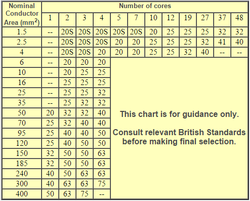
Cable Gland Sizing
A rough gland sizing table is provided below, however reference should be made to the British Standard referenced above.
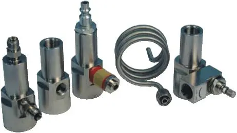
Questions & Answers on Relief Valve Orifice Sizes
What is a Relief Valve?
Relief Valves are mechanical devices designed to operate if an over-pressure situation occurs – they are used to safeguard the plant.
Generally, they are the last line of defence; following on from ESD and operator intervention.
So what is a Relief Valve orifice?
The American Petroleum Institute has developed a series of inlet size, orifice, outlet size combinations for various pressure classes of flanged relief valves. These combinations have been widely adopted by engineers throughout the oil and gas and allied industries.
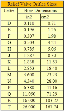
Central to these combinations are a series of fourteen standard orifice sizes each denoted by a letter ranging from D through to T. Each letter refers to a specific effective orifice area.
What do the orifices denote?
The valve sizing engineer (usually a process or instrument engineer) determines the controlling relieving rate from all possible scenarios, then the required relief valve orifice size is determined using the appropriate equation given in API.
Knowing the required relief valve orifice size, an actual orifice size equal to or greater than the calculated orifice size is chosen from a the standard range. The maximum flow through this actual orifice will be the valve’s capacity.
What are the standard orifice sizes?
The full list of letters and corresponding effective area is shown below
Questions & Answers on Dew Point in Compressed Air
What is dew point?
Dew point temperature is a measure of how much water vapor there is in a gas. Water has the property of being able to exist as a liquid, solid, or gas under a wide range of conditions.
To understand the behavior of water vapor, it is first useful to consider the general behavior of gases.
In any mixture of gases, the total pressure of the gas is the sum of the partial pressures of the component gases. This is Dalton’s law and it is represented as follows:
Ptotal = P1 + P2 + P3 …
The quantity of any gas in a mixture can be expressed as a pressure. The major components of air are nitrogen, oxygen, and water vapor, so total atmospheric pressure is composed of the partial pressures of these three gases. While nitrogen and oxygen exist in stable concentrations, the concentration of water vapor is highly variable and must be measured to be determined.
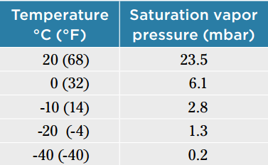
The maximum partial pressure of water vapor is strictly a function of temperature. For example, at 20 °C (68 °F), the maximum partial pressure of water vapor is 23.5 mbar. The value of 23.5 mbar is said to be the “saturation vapor pressure” at 20 °C (68 °F).
In a 20 °C (68 °F), “saturated” environment, the addition of more water vapor results in the formation of condensation. This condensation phenomenon can be exploited to measure water vapor content.
Gas of unknown water vapor concentration is passed over a temperature-controlled surface. The surface is cooled until condensation forms. The temperature at which condensation forms is called the “dew point temperature.”
Because there is a unique correlation between temperature and saturation vapor pressure (remember, the maximum partial pressure of water vapor, also known as saturation vapor pressure, is strictly a function of temperature), measuring the dew point temperature of a gas is a direct measurement of the partial pressure of water vapor.
Knowing the dew point temperature, the corresponding saturation vapor pressure can be calculated or looked up. The following table shows some values for temperature and the corresponding saturation vapor pressure:
What is the difference between dew point and “pressure dew point?”
The term “pressure dew point” is encountered when measuring the dew point temperature of gases at pressures higher than atmospheric pressure.
It refers to the dew point temperature of a gas under pressure. This is important because changing the pressure of a gas changes the dew point temperature of the gas.
What is the effect of pressure on dew point?
Increasing the pressure of a gas increases the dew point temperature of the gas. Consider an example of air at atmospheric pressure of 1013.3 mbar with a dew point temperature of -10 °C (14 °F). From the table above,
the partial pressure of water vapor (designated by the symbol “e”) is 2.8 mbar. If this air is compressed and the total pressure is doubled to 2026.6 mbar, then according to Dalton’s law, the partial pressure of water vapor, e,
is also doubled to the value of 5.6 mbar. The dew point temperature corresponding to 5.6 mbar is approximately -1 °C (30 °F), so it is clear that increasing the pressure of the air has also increased the dew point temperature of the air.
Conversely, expanding a compressed gas to atmospheric pressure decreases the partial pressures of all of the component gases, including water vapor, and
therefore decreases the dew point temperature of the gas. The relationship of total pressure to the partial pressure of water vapor, e, can be expressed as follows:
P1/P2 = e1/e2
By converting dew point temperature to the corresponding saturation vapor pressure, it is easy to calculate the effect of changing total pressure on the saturation vapor pressure.
The new saturation vapor pressure value can then be converted back to the corresponding dew point temperature. These calculations can be done manually using tables, or performed by various kinds of software.
Why is knowledge of dew point in compressed air important?
The importance of dew point temperature in compressed air depends on the intended use of the air. In many cases dew point is not critical (portable compressors for pneumatic tools, gas station tire filling systems, etc.).
In some cases, dew point is important only because the pipes that carry the air are exposed to freezing temperatures, where a high dew point could result in freezing and blockage of the pipes.
In many modern factories, compressed air is used to operate a variety of equipment, some of which may malfunction if condensation forms on internal parts.
Certain water sensitive processes (e.g. paint spraying) that require compressed air may have specific dryness specifications. Finally, medical and pharmaceutical processes may treat water vapor and other gases as contaminants, requiring a very high level of purity.
What is the typical range of dew point temperatures to be found in compressed air?
Dew point temperatures in compressed air range from ambient down to -80 °C (-112 °F), sometimes lower in special cases.
Compressor systems without air drying capability tend to produce compressed air that is saturated at ambient temperature. Systems with refrigerant dryers pass the compressed air through some sort of cooled heat exchanger , causing water to condense out of the air stream.
These systems typically produce air with a dew point no lower than 5 °C (41°F). Desiccant drying systems absorb water vapor from the air stream and can produce air with a dew point of -40 °C (-40 °F) and drier if required.
What are the standards for the quality of compressed air?
ISO8573.1 is an international standard that specifies the quality of compressed air. The standard defines limits for three categories of air quality:
- Maximum particle size for any remaining particles
- Maximum allowable dew point temperature
- Maximum remaining oil content
Each category is given a quality class number between 1 and 6 according to the reference values shown in the table below.
As an example, a system that conforms to ISO8573.1 and is rated for class 1.1.1 will provide air with a dew point no higher than -70 °C (-94 °F). All remaining particles in the air will be 0.1 µm or smaller, and the maximum oil content will be 0.01 mg/m3.
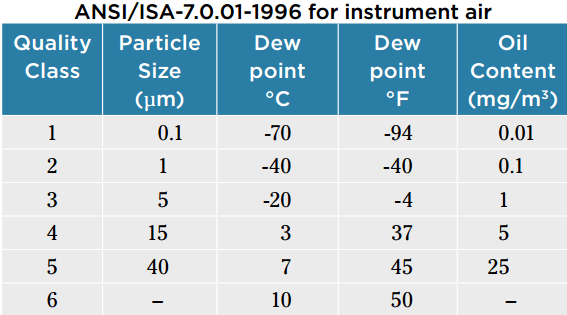
There are other standards for compressed air quality, such as ANSI/ISA- 7.0.01-1996 for instrument air.
How is dew point in compressed air reliably measured?
Some principles of dew point measurement apply to all types of instruments, regardless of manufacturer:
- Select an instrument with the correct measuring range:Some instruments are suitable for measuring high dew points, but not low dew points. Similarly, some instruments are suitable for very low dew points but are compromised when exposed to high dew points.
- Understand the pressure characteristics of the dew point instrument: Some instruments are not suitable for use at process pressure. They can be installed to measure compressed air after it is expanded to atmospheric pressure, but the measured dew point value will have to be corrected if pressure dew point is the desired measurement parameter.
- Install the sensor correctly: Follow instructions from the manufacturer. Do not install dew point sensors at the end of stubs or other “dead end” pieces of pipe where there is no airflow.
If you liked this article, then please subscribe to our YouTube Channel for PLC and SCADA video tutorials.
You can also follow us on Facebook and Twitter to receive daily updates.
Read Next:
- Instrumentation Standards Questions & Answers
- Control Valves Basic Questions & Answers
- Top 100 Instrumentation Engineers Questions & Answers
thank you sir
best for future
Best for interview preparing in short time .I hope you will send me like this valuable notes personally on my mail.
Thanks
Good. Please keep posting more information on Basics.
Nice information u can send me the link on my mail Id
hello sir
i want know what is the difference between DCS and ESD?
DCS stands for Distrubuted control system where as ESD stands for Emergency shut down
DCS mainly used to control a process by using some program on a computer screen with some specific set value, where ESD is to control shutdown valves in a process plant when some Hazards occur or any accident occur in that plant due to some toxic gas leakage or any fire due to flammable substances