Relief Valve and safety valve prevent equipment damage by relieving accidental over-pressurization of fluid systems.
Compare Relief Valve and Safety Valve
The main difference between a relief valve and a safety valve is the extent of opening at the setpoint pressure.
Relief Valve
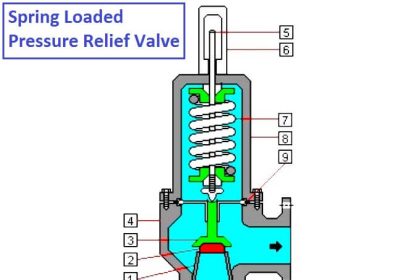
A relief valve, illustrated in Below Figure, gradually opens as the inlet pressure increases above the setpoint. A relief valve opens only as necessary to relieve the over-pressure condition.

Figure : Relief Valve
A safety valve, illustrated in Below Figure, rapidly pops fully open as soon as the pressure setting is reached. A safety valve will stay fully open until the pressure drops below a reset pressure.
The reset pressure is lower than the actuating pressure setpoint. The difference between the actuating pressure setpoint and the pressure at which the safety valve resets is called blowdown.
Blowdown is expressed as a percentage of the actuating pressure setpoint
Relief valves are typically used for incompressible fluids such as water or oil. Safety valves are typically used for compressible fluids such as steam or other gases.
Safety Valve
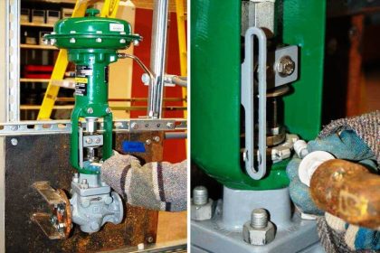
Safety valves can often be distinguished by the presence of an external lever at the top of the valve body, which is used as an operational check.
As indicated in Below Figure, system pressure provides a force that is attempting to push the disk of the safety valve off its seat. Spring pressure on the stem is forcing the disk onto the seat.
At the pressure determined by spring compression, system pressure overcomes spring pressure and the relief valve opens. As system pressure is relieved, the valve closes when spring pressure again overcomes system pressure.
Most relief and safety valves open against the force of a compression spring. The pressure setpoint is adjusted by turning the adjusting nuts on top of the yoke to increase or decrease the spring compression.

Figure : Safety Valve
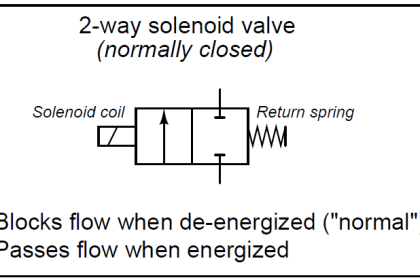
Pilot-Operated Relief Valves
Pilot-operated relief valves are designed to maintain pressure through the use of a small passage to the top of a piston that is connected to the stem such that system pressure closes the main relief valve.
When the small pilot valve opens, pressure is relieved from the piston, and system pressure under the disk opens the main relief valve.
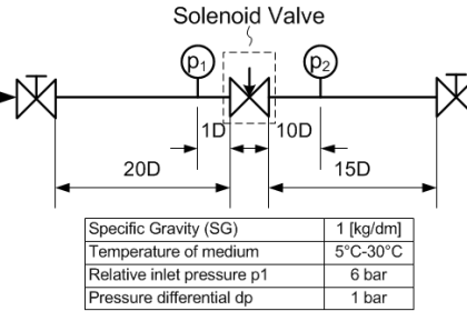
Such pilot valves are typically solenoid operated, with the energizing signal originating from pressure measuring systems.