The purpose of a valve positioner is to ensure the mechanical valve’s position matches the command signal at all times.
Thus, a valve positioner is actually a closed-loop control system in its own right: applying as much or as little pressure to the actuator in order to achieve the commanded valve stem position at all times.
Mechanical valve positioners use levers, cams, and other physical components to achieve this closed-loop control. Electronic valve positioners, such as the Fisher model DVC6000, use an electronic sensor to detect valve stem position, a microprocessor to compare that sensed stem position against the control signal by mathematical subtraction (error = position − signal), then a pneumatic signal converter and relay(s) to send air pressure to the valve actuator.
Electronic Valve positioners
A simplified diagram of a generic electronic valve positioner is shown here:

As you can see from this diagram, there is a lot going on inside an electronic positioner. We have not just one, but two control algorithms working together to maintain proper valve position:
- one monitoring and controlling pressure applied to the actuator (compensating for changes in air supply pressure that might otherwise affect the valve’s position) and
- the other monitoring and controlling stem position itself, sending a cascaded control signal to the pressure control components.
The command signal (sent from the process loop controller, PLC, or other control system) tells the positioner where the valve stem should be positioned. The first controller inside the positioner (PI) calculates how much air pressure at the actuator should be needed to achieve the requested stem position.
The next controller (PID) drives the I/P (current-to-pressure) converter as much as necessary to achieve that pressure.
If anything causes the valve stem to not be at the commanded position, the two controllers inside the positioner work together to force the valve to its proper position.
Not only do electronic valve positioners achieve superior position control when compared to mechanical valve positioners, but their array of sensors and digital communication ability provides a new level of diagnostic data both to maintenance personnel and the supervising control system (if programmed to monitor and act on this data).
Examples of diagnostic data provided by electronic positioners include:
- Supply air pressure
- Actuator air pressure
- Ambient temperature
- Position and pressure errors
- Total valve stem travel (like an odometer in an automobile)
Additionally, the microprocessor embedded within an electronic valve positioner is capable of performing self-tests, self-calibrations, and other routine procedures traditionally performed by instrument technicians on mechanical valve positioners.
Having access to such measurements as total valve stem travel even allows an electronic positioner to predictively calculate packing wear-out time, automatically flagging a maintenance alarm notifying operators and/or instrument technicians when the valve’s stem packing will need to be replaced!
A useful capability of some “smart” valve positioners – since they monitor actuator air pressure in addition to stem position – is the ability to maintain a respectable degree of valve control in the event of a stem position sensor failure.
If the microprocessor detects a failed (off-scale) position feedback signal, it may be programmed to continue operating the valve based on pressure alone: adjusting the applied air pressure to the valve actuator according to the pressure/position function it has recorded in the past.
While not strictly functioning as a positioner any more since it cannot sense valve stem position, it may still fulfill its role as a volume booster (compared to the flow capacity of a typical I/P) and give reasonable control over the valve where any other (non-smart) valve positioner would actually make matters worse in the event of losing its stem position feedback.
With any purely mechanical positioner, the control valve will typically “saturate” either fully open or fully closed if the stem position feedback linkage falls off. Not so with the best “smart” positioners!
Perhaps the most significant diagnostic data provided by an electronic positioner is the comparison of actuator pressure versus stem position, usually expressed in the form of a graph.
Actuator pressure is a direct reflection of force applied by the actuator to the valve stem, since the relationship between force and pressure for either a piston or a diaphragm is simply F = PA, where area (A) is constant.
Thus, a comparison of actuator air pressure versus stem position is really an expression of force-versus-position for the valve.
This so-called valve signature is incredibly useful in identifying and correcting such problems as excessive packing friction, valve trim interference, and plug/seat fit problems.
A screenshot showing a “valve signature” (taken from an Emerson software product called ValveLink, as part of their AMS suite) appears here, showing the behavior of an air-to-open Fisher E-body globe valve:

Two plots of actuator pressure versus stem position are shown in this graph, one red and one blue.
The red graph shows the valve’s response in the opening direction where additional pressure is required to overcome packing friction as the valve moves open (up).
The blue graph shows the valve as it closes, less pressure applied to the diaphragm now to allow the spring’s compression to overcome packing friction as the valve moves closed (down) to its resting state.
The sharp turns at each end of this graph show where the valve stem reaches its end positions and cannot move farther despite further changes in actuator pressure.
Each plot is roughly linear in accordance with Hooke’s Law describing the behavior of the valve spring, where the force applied to a spring is directly proportional to the displacement (compression) of that spring: F = kx.
Any departure from a single linear plot indicates some other force(s) besides spring compression and pneumatic force acting on the valve stem.
This is why we see two plots vertically offset from each other: packing friction is another force acting on the valve stem in addition to spring compression and the force exerted by air pressure on the actuator diaphragm.
The relatively small magnitude of this offset as well as its consistency indicates that packing friction in this valve is “healthy.” The more packing friction this valve experiences, the more vertically-offset the two plots will be.
The sharp down-turn at the left-hand end of the graph where the valve plug contacts the seat is called the seating profile.
Located at the end of the plot where the valve closes off, the seating profile holds much useful information about the physical condition of the plug and seat.
As these trim parts wear in a control valve, the shape of the seating profile changes accordingly. Irregular seating profiles may diagnose seat erosion, galling, or a number of other maladies.
By zooming in on the lower-left end of the valve signature graph, the seating profile may be examined in fine detail.
A seating profile taken of a Fisher E-body globe valve in pristine condition appears here:

If the maintenance staff of a particular facility are diligent enough to record the valve signatures of its control valves after assembly or rebuild, the “original” signature of any particular control valve may be compared against the signature of the same control valve taken at any later date, allowing qualitative determinations of wear without having to disassemble the valves for inspection.
Interestingly, this relationship of actuator pressure (force) to stem position is also available in the electronic positioners used with some modern electrically-actuated valves.
In the case of an electric actuator, force applied to the valve stem directly relates to motor current, which is easily measured and interpreted by the electronic positioner.
Thus, even with a different actuator technology, the same kind of diagnostic data may be presented in graphical form for the purpose of more easily diagnosing valve problems.
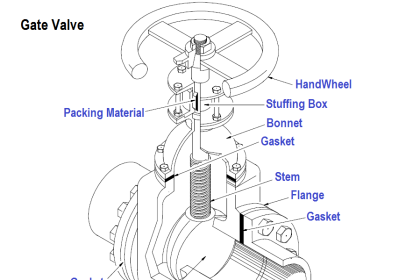
These diagnostics apply even to open/close motor-operated valves not used for throttling service, and are especially useful on gate, plug, and ball-type shut-off valves where seat engagement is substantial for tight shut-off.