The following points are considered during level sensors selection or during time of plant design.
They are
- Pressure Vessel Connection
- Vessel bottom connection
- Range selection
- Material
- Environment
- Standpipes vs. sensor cages
- Level sketches
- Data
- Emulsion
- Calibration
- Stilling wells
- Centring disk
- Control and safety
- Heat tracing
- Maintenance access
- Service capabilities
1. Pressure Vessel Connection
Level instrument tapping on vessel outlet piping are not recommended. API RP 551 (reaffirmed in 2007, section 3.2.4) provides guidance with respect to a dynamic flow connection.
Level measurement instruments should be isolatable for maintenance, dismantling/removal and calibration without affecting production, except when stopping the production for such activities is deemed acceptable.
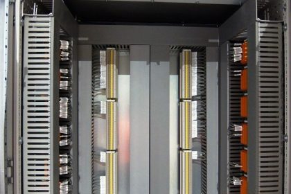
Level instruments may be internally or externally mounted. They should be provided with individual isolation facilities allowing for sensor removal, and cage/chamber cleaning (see Figure 1).
As far as possible, the measurement in the sensor cage/chamber should be representative of the actual level in the vessel. To display a representative level, this might require additional tapping/connection on the vessel.
Isolation valves ID (e.g. used for DP or Radar) should be the same as the nozzle ID.
Level instrument flange should be designed in accordance with the piping/vessel code and material. Flange facing should be free of any coating/insulation and suitable for receiving the piping/vessel gaskets.
Note: Irrespective of the location of instrument nozzles, the weld edge distances requirement from ‘Piping’ Code such as ASME VIII and/or PD 5500 Vessels should have adequate access/distance for constructability and inspection.
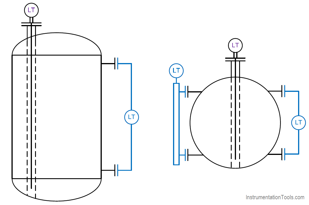
Figure 1 Pressure vessel mounting principle
2. Vessel Bottom Connection
Connections to bottom vessel heads should be avoided since exact positioning is difficult, dead legs are created and often the vessel skirt has to be penetrated.
3. Range Selection
The normal operating/alarm/trip settings should be defined by a combination of process/vessel/instrument operational limits.
Measurement ranges used for process control system (LT for BPCS and LG) and safety instrumented systems (LT for SIS) should generally have the same range and process tapping elevations to allow for continuous monitoring of any discrepancy between various measurements.
However, if for accuracy or sensitivity reasons this cannot be achieved, then the process control system measurement range should cover the safety instrumented systems measurement range.
The definition of alarm and trip levels should be reviewed between the process, piping and instrumentation specialists to ensure feasibility. Appropriate (minimum) differential between the alarm and the trip should be considered.
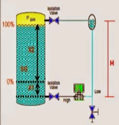
The measuring range should be sketched/defined as in Figure 2:
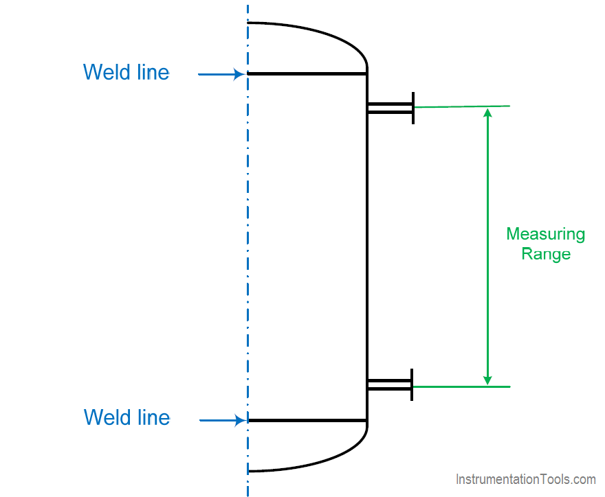
Figure 2 Measuring range
4. Material
All materials used for the level measurement should be selected according to the equipment (e.g. piping, vessel, tank…) and the process fluids.
Unless otherwise specified, wet parts of instrumentation devices (displacer, float, diaphragm..) should be minimum AISI 316 or 316 L SS.
Special care should be taken for selection of material (e.g. gold plated membrane) in contact with low molecular mass fluid or if hydrogen permeation is expected.
Material of housing should be AISI 316 or 316 L SS for offshore. Alternatively, other materials such as A365 grade aluminum (epoxy painted) or GRP may also be used.
5. Environment
All devices used for level measurement should be suitable for their environmental conditions. This applies to the temperature, humidity, electromagnetic compatibility, ingress protection as well as the hazardous area. The relevant certification should be provided.
Weight and available space constraints particularly to allow removal of the instrument should be taken into account when selecting a level measurement technology.
Level Instruments should be assessed for the extremes of weather protection including sunshades and protection boxes as required.
6. Standpipes vs. Sensor cages
The terms standpipe and sensor cages are often mixed up. In order to clarify, the following definitions are used:
Standpipe/Bridle
This is an external extension of the pressure vessel, to which multiple instruments can be connected. A standpipe should follow the pressure vessel code. Usually no instrument is installed inside the standpipe itself. Isolation valves may be used between vessel and standpipe (as per API RP 551 reaffirmed 2007, Figure 12).
Each instrument connected should have its own isolation valves, vents and drain to facilitate maintenance. The distance between the standpipe and the vessel nozzle should not exceed 1 – 1.5 m.
Long connections could potentially cause temperature gradients, formation of hydrate and reduction in level coupling between the standpipe and the vessel (refer to API RP 551 reaffirmed 2007, Figure 12).
Sensor cage/chamber
This is an individual cage/chamber in which the level sensor is installed, part of a single level instrument. The sensor cage/chamber can be attached either directly to the pressure vessel or to a standpipe. The sensor cage/chamber should have dedicated process isolation, vent and drain valves provided.
Drain valves should be installed at the bottom connection of the sensor cage and provisions should be made for the appropriate disposal of the drained material. Vent valves are provided to allow depressurization of the instrument prior to draining. In toxic services, drains and vents should be piped away from the instrument to a safe area or disposal system.
Care should be taken to reduce the temperature gradient between the vessel and the Standpipe/bridle/sensor cage/chamber.
Standpipes, bridles, sensor cages and chambers can be reviewed and assessed for thermal insulation and trace heating requirements.
7. Level Sketches
Level sketches should be prepared at an early stage of the engineering. Level sketches should include details related to nozzle sizes and heights, vessel internal and external supports, material, sensor/source location, etc. in line with the Product Manufacturer recommendation.
Level sketches should indicate all level related instruments (transmitters, gauges, switches) for all applications (i.e. BPCS and/or SIS) with tapping connections and normal operating/alarm/trip settings.
Level sketches should describe level threshold in both ‘length’ and ‘%’ measured range.
Note: Sufficient clearance to facilitate level instrument and chamber/cage draining to a safe location/closed drain system should be incorporated into the design.
8. Data
Process data should be carefully addressed with all detailed fluid features as well as the different layers to be measured.
From the design perspectives the BPCS level measurement uncertainty should be better than +/− 5% of the reading and the SIS level measurement uncertainty should be better than +/− 2% of the reading.
For floating facilities (e.g. FPSO), the design should take into account the vessel motion (e.g. pitch, roll) which can influence the measurement range and technology selection. Level sketches should integrate the margins of range and thresholds due to the vessel motion.
Local radiation safety requirements, local radio frequency requirements and operational requirements (radiography) and how such events are managed together with environmental data should be taken into account.
Process data
For each level instrument the minimum following process data range (e.g. min, max, operating, and design) should be defined:
- process data (e.g. density/SG, temperature, pressure, dielectric, viscosity…)
- specific service (e.g. corrosive, cryogenic…)
- level measurement requirements (e.g. safety or control application, alarms and trip values…)
- presence of other nucleonic isotopes in the fluid
- presence of salt
- presence of oil‐film/build‐up
- presence of sand/water/emulsion/oil/foam
- the type and name of the substance/process fluid to be measured.
Level data
For each level measurement, the following data should be defined as a minimum:
- available nozzle diameter and flange connection
- vessel internal and external arrangements and layouts
- vessel material composition and wall thickness
- hook‐up, location in the vessel and installation
- nucleonic source and detectors calculation note(s)
- nucleonic source intensity
- geometry, distance and location of nucleonic sources and detectors
- operation and maintenance manuals as well as particular instructions (e.g. adjustment and calibration interventions)
- calibration procedure (in factory and in operation)
- additional screening around final nucleonic source container installation location
- dip pipe features (material, thickness, flange diameter…)
- procedures for handling and storage
- certificates of licensing and regulatory requirements…
9. Emulsion
An emulsion is a mixture of two or more liquids that are normally immiscible. Emulsions are part of a more general class of two‐phase systems of matter called colloids.
Although the terms colloid and emulsion are sometimes used interchangeably, emulsion should be used when both the dispersed and the continuous phase are liquids.
As an example, oil and water can form, first, an oil‐in‐water emulsion, wherein the oil is the dispersed phase, and water is the dispersion medium.
Second, they can form a water‐in‐oil emulsion, wherein water is the dispersed phase and oil is the external phase. Multiple emulsions are also possible, including a ‘water‐in‐oil‐in‐water’ emulsion and an ‘oil‐in‐water‐in‐oil’ emulsion.
Particular attention should be paid to any interface measurement in the presence of emulsion. Density of water in oil emulsion will change depending on water fraction. At high water content (approximately 80% of water‐in‐oil) the density is comparable to the water.
Then density decreases, not necessary linearly, with the decreasing of the volume fraction of water. At a low water content (approximately 20% of water‐in‐oil), the density drops sharply to the oil value. This means that the emulsion density is not constant.
However, the emulsion density can be seen as the average of the oil and the water density. Dielectric or conductivity values of the emulsion follow the same principle of non‐linear dispersion. This implies that the emulsion cannot be ‘seen’ easily as a single two fluids interface.
Note: The foam also is a non‐uniform fluid; density, dielectric and conductivity parameters vary in a stochastic manner.
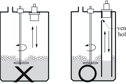
An emulsion layer at the interface of two fluids may or may not be seen by the instrument depending upon the hook‐up arrangement. When using a sensor cage/stand pipe, the following can be considered:
Figure 3: the interface level device in the sensor cage/stand pipe does not ‘see’ the emulsion in the vessel, so the measured value only represents the average interface level
Figure 4: the interface level device in the sensor cage/standpipe ‘sees’ the emulsion layer so the measured value represents accurately the interface level
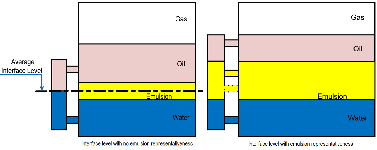
Figure 3 (Left) : Interface level with no emulsion representativeness
Figure 4 (Right) : Interface level with emulsion representativeness
Note: the accuracy of the interface level measurement in the presence of the emulsion will depend upon the number of nozzles provided, the selected level sensor technology, the correct specification of the technical data, i.e. SG and thorough commissioning and calibration of the instrument.
The number of nozzles that can be provided on a tank or vessel is often limited due to the space ant the mechanical integrity of the vessel or tanks. Thus, if accurate level measurement is required in the presence of emulsion, a direct top mounted technology level should be considered.
10. Calibration
Calibration should be performed prior to the factory acceptance test and prior to shipment. A calibration certificate should be provided that detail the traceability of the test equipment used.
Site calibration should be performed to ensure the factory calibration has not deteriorated during transportation and any site specific requirements are accommodated. Any shipping stops, seals, plastic fitments, temporary grommet seals or guides to ensure safe shipping should be removed prior to fitting and mechanical completion.
Particular attention should be paid to calibration of Radar, GWR, Capacitance and Nucleonic instruments. The lower range value should be calibrated without any process fluids, but as far as possible with all vessel utilities (e.g. energy for electro dehydrators) present.
This should take into account any signal noise/disturbance. The higher range value should be calibrated with the maximum fluid level to be measured. Special tools should be provided. Any special sensor or probe coating should not influence the calibration.
Arrangement for in‐line calibration and flushing of the instrument is recommended.
Onsite verification should be completed for instruments assigned as part of a LOP, e.g. SIS and critical alarms.
11. Stilling wells
A stilling well is a perforated pipe to allow free movement of fluid. This pipe is equipped with a top mounted flange which is supported at the bottom of the vessel. For a long still well, support should be provided along its length; however these supports should not affect the measurement.
Stilling wells provide a stable gauge reference point (limit vertical movement), and provide a relatively ‘quiet’ product surface during filling and emptying of the vessel, especially if ‘swirl’ exists.
Stilling wells may act as a ‘wave guide’ for the radar energy. The well helps to concentrate the emitted signal and minimize the signal loss. The loss of signal is generally due to a low product reflectivity (caused by a low dielectric constant) or surface phenomena like ‘boiling off’ and ‘vapour mist’.
Stilling wells should not be used with viscous fluid, dirty fluid or fluid‐film‐buildup. Stilling well should be one piece from the top to the bottom (i.e. no gaps).
The following features should be considered for stilling well:
- AISI 316 SS minimum with smooth roughness ≤ 6.3 μm (no welding parts)
- one piece from the nozzle flange with constant diameter.
Stilling wells slot width/holes diameter should generally be 1/10 of the stilling well diameter with a minimum of 0.635 cm. Spacing between slots/holes should minimum be 15 cm.
Slots/holes should be deburred and their quantity minimized. Holes shape may be slotted or circular. Holes should be on both sides of the stilling well, in order to minimize the risk of plugging especially for waxing service.
Stilling well diameter should be minimum 20 cm (as per API MPMS § 3.1A).
Stilling well design and construction should be approved by the Product Manufacturer.
12. Centring disk
Centring disk used in stilling wells should be compatible with the fluid properties (build‐up, viscosity…) and mounted outside the measuring range.
Consideration should be taken into account when using a weighted bottom mounted on the rod instead of using centring disks. Centring disks should be provided as per the Product Manufacturer recommendation.
13. Control and safety
Level measurements should be designed to ensure that the likelihood of common cause, common mode and dependent failures between monitoring, control or safety protection layers are addressed.
This design should consider the following:
- independency between protection layers
- diversity between protection layers
- physical separation between different protection layers
- common cause failures between protection layers.
As such, differing measurement principles are recommended for control and safety functions.
With reference to ISO 10418 issue 2003, § 6.2.9.
“The two levels of protection shall be independent of, and in addition to, the control devices used in normal process operation” it is suggested to change the recommendation to a requirement for separate nozzles.”
The safety function should provide a reliable and sufficiently fast detection of process upsets. Since the control function can both work as back‐up as well as comparison of the safety function equal performance is recommended for control (accuracy and trip point should be considered).
If shutdown measurements require input from other variables (e.g. temperature and pressure) to calculate the correct value, these inputs should be separate for control and shutdown functions.
It should not be possible to inadvertently isolate instrumentation for shutdown functions from the process.
Level instrumentation used on process vessels, should be designed so that one of the level instruments used for control and safety, should not be affected by radioactive disturbance from tracers, scale and x‐rays.
Level gauge is recommended for the entire measuring range. Level gauges are used for local operation and as reference to level instrumentation.
If multiple level devices are required (e.g. one device for control and second device for alarm, or potentially several devices as part of a SIS), the use of diverse level technologies should be assessed.
Consideration should be given to comparison of different devices used on the same duty, with cross comparison and alarms function from a deviated percentage, i.e. 5%.
14. Heat tracing
All instrument nozzles should be located such that the risk of blockage and solidification in the nozzle is minimized. If there is risk of hydrate formation or freezing in the instrument nozzles or instrument impulse lines, application of heat tracing should be considered.
Note, however, that there may be safety requirements connected with the heat tracing, i.e. hazardous area equipment requirements or over temperature protection.
15. Maintenance access
All level instruments should be designed for long term stability and operation. Intervals for planned production stops are normally two years or longer.
Relief/drainage tubing or pipe should be routed to a safe location according to area requirements, i.e. to a safe location/closed drain system.
Maintenance operation should take into account the hazardous area certification type e.g. Ex ia/ib, Ex d…
Level instruments do not normally require readability from deck. Level gauges or indicators should be readable from deck or permanent platform.
Isolation valves should be available for operation.
16. Service capabilities
During the design phase it is recommended to include the Product Manufacturer in the proper design, construction and installation of the facilities (e.g. level sketch, hook‐up, stilling wells).
At site, the Product Manufacturer should have the capability of assisting in the commissioning and start‐up activities, providing specific training, performing site calibration and issuing specific detailed maintenance procedure for equipment cleaning and replacement.
The Product Manufacturer should provide a comprehensive spares listing, part numbers and the time taken to expedite basic consumable items.
The Product Manufacturer should provide obsolescence plan to indicate spare part availability for each model for users to plan for upgrading or stocking plan as appropriate. Life cycle cost (i.e. total cost of ownership) may be evaluated for selection of measurement technology.
These spares should be added to the maintenance management systems that logs and details the installed device on the specific site and installation.
Abbreviations :
- BPCS : Basic Process Control System
- LT Level Transmitter
- LG Level Gauge
- DP Differential Pressure
- ID Internal Diameter
- SIS Safety Instrumented System
- SS Stainless Steel
- FPSO Floating, Production, Storage and Offloading
Source : International Association of Oil & Gas Producers
Acknowledgements : IOGP Instrumentation and Automaton Standards Subcommittee (IASSC), BG Group, BP, Endress + Hauser, Emerson, Honeywell, Krohne, Petrobras, PETRONAS Carigali Sdn Bhd, Repsol, Siemens, Statoil, Total, Vega, Yokogawa.