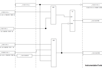
To understand the hard-wired control logic concept, let us examine a relay control circuit where a pressure switch activates an alarm light.
Hard-Wired Control Logic for the Pressure Alarm
Solution:
Here we used simple applications to understand the hardwired control logic. In industry, we are using PLC for logic but sometimes for simple applications, we can use hardwired control logic.
However, this logic is complex for large applications, but we can use it for small applications.
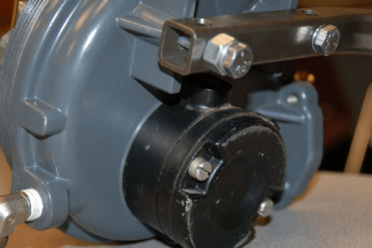
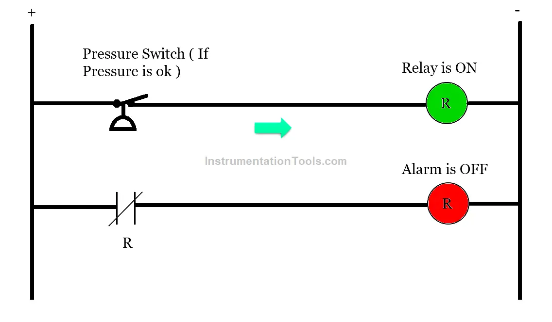
As shown in above figure 1, we used a pressure switch and alarm lamp. Pressure is set in the pressure switch around 10 Psi. Here we used NC contact of the pressure switch so when pressure is ok, the relay is in actuated condition so the alarm lamp will be ON.
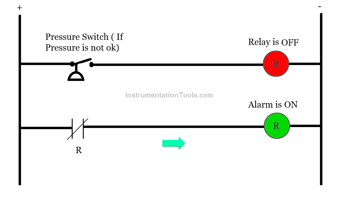
As shown in above figure 2, if pressure is below 10Psi then the relay will be OFF so the NC contact of the relay will remain healthy. So that alarm lamp will be ON.
Disclaimer: The example application presented here is intended solely for illustrative purposes and may differ from real-world applications. The logic implemented in this example is not the only way to achieve the same function; various methods can be used. The parameters and graphical depictions used herein are also for explanatory reasons and may vary in actual setups. Please note that this example does not account for all possible safety interlocks or additional features that might be present in a real-world scenario.