Inst ToolsInst ToolsInst Tools
  • Courses
  • Automation
    • PLC
    • Control System
    • Safety System
    • Communication
    • Fire & Gas System
  • Instrumentation
    • Design
    • Pressure
    • Temperature
    • Flow
    • Level
    • Vibration
    • Analyzer
    • Control Valve
    • Switch
    • Calibration
    • Erection & Commissioning
  • Interview
    • Instrumentation
    • Electrical
    • Electronics
    • Practical
  • Q&A
    • Instrumentation
    • Control System
    • Electrical
    • Electronics
    • Analog Electronics
    • Digital Electronics
    • Power Electronics
    • Microprocessor
  • Request
Search
  • Books
  • Software
  • Projects
  • Process
  • Tools
  • Basics
  • Formula
  • Power Plant
  • Root Cause Analysis
  • Electrical Basics
  • Animation
  • Standards
  • 4-20 mA Course
  • Siemens PLC Course
Reading: Series Resistance
Share
Font ResizerAa
Inst ToolsInst Tools
Font ResizerAa
  • Courses
  • Design
  • PLC
  • Interview
  • Control System
Search
  • Courses
  • Automation
    • PLC
    • Control System
    • Safety System
    • Communication
    • Fire & Gas System
  • Instrumentation
    • Design
    • Pressure
    • Temperature
    • Flow
    • Level
    • Vibration
    • Analyzer
    • Control Valve
    • Switch
    • Calibration
    • Erection & Commissioning
  • Interview
    • Instrumentation
    • Electrical
    • Electronics
    • Practical
  • Q&A
    • Instrumentation
    • Control System
    • Electrical
    • Electronics
    • Analog Electronics
    • Digital Electronics
    • Power Electronics
    • Microprocessor
  • Request
Follow US
All rights reserved. Reproduction in whole or in part without written permission is prohibited.
Inst Tools > Blog > Electrical Theory > Series Resistance

Series Resistance

Last updated: July 23, 2018 12:12 pm
Editorial Staff
Electrical Theory
1 Comment
Share
5 Min Read
SHARE

The total resistance in a series circuit is equal to the sum of all the parts of that circuit, as shown in below equation.

RT =R1 +R2 +R3 …      etc.

where
RT = resistance total
R1 ,R2 , and R3 = resistance in series

Example:

A series circuit has a 60Ω, a 100Ω, and a 150Ω resistor in series (Figure 18). What is the total resistance of the circuit?

Calculate Resistance in Series Circuit

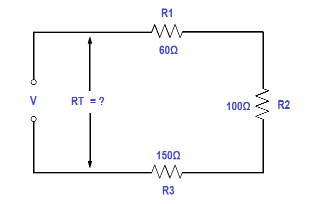
Figure 18 Resistance in a Series Circuit

Solution:

RT =R1 +R2 +R3

RT = 60 + 100 + 150

RT = 310 Ω

The total voltage across a series circuit is equal to the sum of the voltages across each resistor in the circuit (Figure 19) as shown in below equation.

VT =V1 +V2 +V 3 …     etc.

where

VT = total voltage

V1 = voltage across R1

V2 = voltage across R2

V3 = voltage across R3

Voltage Drop in a Series Circuit

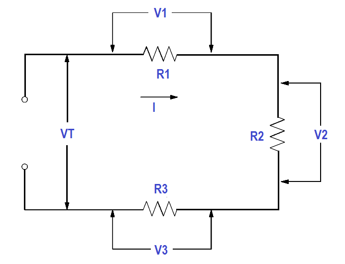
Figure 19 Voltage Drops in a Series Circuit

Ohm’s law may now be applied to the entire series circuit or to individual component parts of the circuit. When used on individual component parts, the voltage across that part is equal to the current times the resistance of that part. For the circuit shown in Figure 20, the voltage can be determined as shown below.

V1= IR1
V2 = IR2
V3 = IR3

VT = V1 + V2 + V3

VT = 10 volts + 24 volts + 36 volts
VT = 70 volts

Total Voltage in a Series Circuit

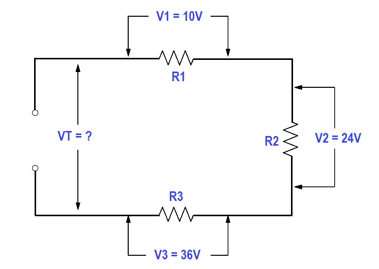
Figure 20 Voltage Total in a Series Circuit

To find the total voltage across a series circuit, multiply the current by the total resistance as shown in below equation.

VT = I . RT

where

VT = total voltage
I = current
RT = total resistance

Example 1:

A series circuit has a 50Ω, a 75Ω, and a 100Ω resistor in series (Figure 21). Find the voltage necessary to produce a current of 0.5 amps.

Series Circuit Resistance Calculation

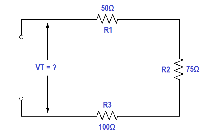
Figure 21 Example 1 Series Circuit

Solution:

Step 1: Find circuit current. As we already know, current is the same throughout a series circuit, which is already given as 0.5 amps.

Step 2: Find RT

RT = R1 + R2 + R3

RT = 50 Ω + 75 Ω + 100 Ω

RT = 225 Ω

Step 3: Find VT .

Use Ohm’s law. VT = I . RT

VT = 0.5 x 225

VT = 112.5 volts

Example 2:

A 120 V battery is connected in series with three resistors: 40Ω, 60Ω, and 100Ω (Figure 22). Find the voltage across each resistor.

Series Circuit Voltage Calculations

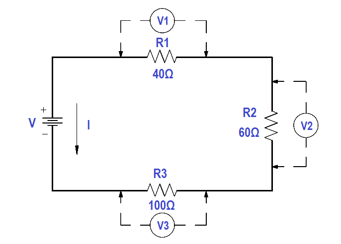
Figure 22 Example 2 Series Circuit

Solution:

Step 1: Find total resistance.

RT = R1 + R2 + R3

RT = 40 Ω + 60 Ω + 100 Ω

RT = 200 Ω

Step 2: Find Circuit Current (I) .

Use Ohm’s law. VT = I . RT

Solving for I

I = VT/RT

I = 120/200 = 0.6 amps

Step 3: Find the voltage across each component.

V1= IR1
V1 = (0.6 amps)(40 Ω)
V1 = 24 volts

V2 = IR2
V2 = (0.6 amps)(60 Ω)
V2 = 36 volts

V3 = IR3
V3 = (0.6 amps)(100 Ω)
V3 = 60 volts

The voltages of V1 ,V2 , and V3 in Example 2 are known as “voltage drops” or “IR drops.” Their effect is to reduce the available voltage to be applied across the other circuit components. The sum of the voltage drops in any series circuit is always equal to the applied voltage. We can verify our answer in Example 2 by using below equation

VT = V1 + V2 + V3

120 volts = 24 volts + 36 volts + 60 volts

120 volts = 120 volts

Don't Miss Our Updates
Be the first to get exclusive content straight to your email.
We promise not to spam you. You can unsubscribe at any time.
Invalid email address
You've successfully subscribed !

Continue Reading

Calculate Power in Series RC Circuit
Simplified Formulas for Parallel Circuit Resistance Calculations
Ampere Hour Meter
Single Phase AC Induction Motors
Calculate Power in Parallel RC Circuit
Impedance in RL Circuits
Share This Article
Facebook Whatsapp Whatsapp LinkedIn Copy Link
Share
1 Comment
  • Emmanuel says:
    March 7, 2021 at 4:42 am

    Good and interested

    Reply

Leave a Reply Cancel reply

Your email address will not be published. Required fields are marked *

Stay Connected

128.3kFollowersLike
69.1kFollowersFollow
210kSubscribersSubscribe
38kFollowersFollow

Categories

Explore More

Multimeter & Megger Principle
Parallel Circuit
Synchronous Motors
Battery Hazards
Circuit Breaker Control Circuit
Three Phase Wattmeter
What is Electricity ?
Generator Action in a Motor

Keep Learning

DC Generator

DC Generator

Voltage Divider

Voltage Divider

Measuring Circuit Voltage

Voltmeters

3-Wire, Three-Phase Delta Wiring System

3-Wire, Three-Phase Delta Wiring System

How to Measure Specific Gravity of Battery

How to Measure Specific Gravity of Battery

Chemical Battery

Batteries

Generator Action in a Motor

What is Synchroscope ?

Series - Wound DC Motor

Series-Wound Motor

Learn More

Loop Calibrator to Simulate a 4-20 mA Signal

Loop Calibrator to Simulate a 4-20 mA Signal

Basic Process Control System

Basic Process Control System

Analyzers Questions and Answers

NO2 Analyzer Questions & Answers

Top 20 Service Business Opportunities in the Instrumentation Industry

Top 20 Instrumentation Service Business Opportunities in the Industry

Power Electronics Projects

Top 100 Power Electronics Projects for Engineering Students

Deaerator Pressure and Level Control System in Power Plants

Deaerator Pressure and Level Control System in Power Plants

Compressor IP Case Discharge Temperature Gradually Increases

Compressor IP Case Discharge Temperature Gradually Increases

UL 489 Circuit Breaker

Difference Between UL489 and UL1077

Menu

  • About
  • Privacy Policy
  • Copyright

Quick Links

  • Learn PLC
  • Helping Hand
  • Part Time Job

YouTube Subscribe

Follow US
All rights reserved. Reproduction in whole or in part without written permission is prohibited.
Welcome Back!

Sign in to your account

Username or Email Address
Password

Lost your password?