Why Ground?
Poor grounding not only contributes to unnecessary downtime, but a lack of good grounding is also dangerous and increases the risk of equipment failure. Without an effective grounding system, we could be exposed to the risk of electric shock, not to mention instrumentation errors, harmonic distortion issues, power factor problems and a host of possible intermittent dilemmas. If fault currents have no path to the ground through a properly designed and maintained grounding system, they will find unintended paths that could include people.
The following organizations have recommendations and/or standards for grounding to ensure safety:
OSHA (Occupational Safety Health Administration) »
NFPA (National Fire Protection Association) »
ANSI/ISA (American National Standards Institute and Instrument Society of America) »
TIA (Telecommunications Industry Association) »
IEC (International Electrotechnical Commission) »
CENELEC (European Committee for Electrotechnical Standardization) »
IEEE (Institute of Electrical and Electronics Engineers) »
However, good grounding isn’t only for safety; it is also used to prevent damage to industrial plants and equipment. A good grounding system will improve the reliability of equipment and reduce the likelihood of damage due to lightning or fault currents. Billions are lost each year in the workplace due to electrical fires. This does not account for related litigation costs and loss of personal and corporate productivity.
Why Test Ground Systems?
Over time, corrosive soils with high moisture content, high salt content, and high temperatures can degrade ground rods and their connections. So although the ground system when initially installed, had low earth ground resistance values, the resistance of the grounding system can increase if the ground rods are eaten away.
That is why it is highly recommended that all grounds and ground connections are checked at least annually as a part of your normal Predictive Maintenance plan. During these periodic checks, if an increase in resistance of more than 20 % is measured, the technician should investigate the source of the problem, and make the correction to lower the resistance, by replacing or adding ground rods to the ground system.
What is a Ground and What Does it Do?
The NEC, National Electrical Code, Article 100 defines a ground as: “a conducting connection, whether intentional or accidental between an electrical circuit or equipment and the earth, or to some conducting body that serves in place of the earth.” When talking about grounding, it is actually two different subjects: earth grounding and equipment grounding. Earth grounding is an intentional connection from a circuit conductor, usually the neutral, to a ground electrode placed in the earth. Equipment grounding ensures that operating equipment within a structure is properly grounded. These two grounding systems are required to be kept separate except for a connection between the two systems. This prevents differences in voltage potential from a possible flashover from lightning strikes. The purpose of a ground besides the protection of people, plants and equipment is to provide a safe path for the dissipation of fault currents, lightning strikes, static discharges, EMI and RFI signals and interference.
What is a Good Ground Resistance Value?
There is a good deal of confusion as to what constitutes a good ground and what the ground resistance value needs to be. Ideally a ground should be of zero ohms resistance.
There is not one standard ground resistance threshold that is recognized by all agencies. However, the NFPA and IEEE have recommended a ground resistance value of 5.0 ohms or less.
The NEC has stated to “Make sure that system impedance to ground is less than 25 ohms specified in NEC 250.56. In facilities with sensitive equipment it should be 5.0 ohms or less.”
The Telecommunications industry has often used 5.0 ohms or less as their value for grounding and bonding.
The goal in ground resistance is to achieve the lowest ground resistance value possible that makes sense economically and physically.
Grounding Basics
Components of a Ground Electrode
- Ground conductor
- Connection between the ground conductor and the ground electrode
- Ground electrode
Locations of Resistances
- The ground electrode and its connection
The resistance of the ground electrode and its connection is generally very low. Ground rods are generally made of highly conductive/low resistance material such as steel or copper. - The contact resistance of the surrounding earth to the electrode
The National Institute of Standards (a governmental agency within the US Dept. of Commerce) has shown this resistance to be almost negligible provided that the ground electrode is free of paint, grease, etc. and that the ground electrode is in firm contact with the earth. - The resistance of the surrounding body of earth
The ground electrode is surrounded by earth which conceptually is made up of concentric shells all having the same thickness. Those shells closest to the ground electrode have the smallest amount of area resulting in the greatest degree of resistance. Each subsequent shell incorporates a greater area resulting in lower resistance. This finally reaches a point where the additional shells offer little resistance to the ground surrounding the ground electrode.
So based on this information, we should focus on ways to reduce the ground resistance when installing grounding systems.
What Affects the Grounding Resistance?
First, the NEC code (1987, 250-83-3) requires a minimum ground electrode length of 2.5 meters (8.0 feet) to be in contact with soil. But, there are four variables that affect the ground resistance of a ground system:
- Length/depth of the ground electrode
- Diameter of the ground electrode
- Number of ground electrodes
- Ground system design
Length/Depth of the Ground Electrode
One very effective way of lowering ground resistance is to drive ground electrodes deeper. Soil is not consistent in its resistivity and can be highly unpredictable. It is critical when installing the ground electrode, which it is below the frost line. This is done so that the resistance to ground will not be greatly influenced by the freezing of the surrounding soil.
Generally, by doubling the length of the ground electrode you can reduce the resistance level by an additional 40 %. There are occasions where it is physically impossible to drive ground rods deeper—areas that are composed of rock, granite, etc. In these instances, alternative methods including grounding cement are viable.
Diameter of the Ground Electrode
Increasing the diameter of the ground electrode has very little effect in lowering the resistance. For example, you could double the diameter of a ground electrode and your resistance would only decrease by 10 %.
Number of Ground Electrodes
Another way to lower ground resistance is to use multiple ground electrodes. In this design, more than one electrode is driven into the ground and connected in parallel to lower the resistance. For additional electrodes to be effective, the spacing of additional rods need to be at least equal to the depth of the driven rod. Without proper spacing of the ground electrodes, their spheres of influence will intersect and the resistance will not be lowered.
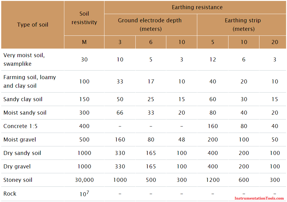
To assist you in installing a ground rod that will meet your specific resistance requirements, you can use the table of ground resistances, below. Remember, this is to only be used as a rule of thumb, because soil is in layers and is rarely homogenous. The resistance values will vary greatly.
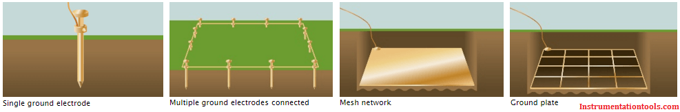
Ground System Design
Simple grounding systems consist of a single ground electrode driven into the ground. The use of a single ground electrode is the most common form of grounding and can be found outside your home or place of business. Complex grounding systems consist of multiple ground rods, connected, mesh or grid networks, ground plates, and ground loops. These systems are typically installed at power generating substations, central offices, and cell tower sites.
Complex networks dramatically increase the amount of contact with the surrounding earth and lower ground resistances.


Good one. Thanks for sharing your knowledge with all of us.