In previous articles, we got to know some of the basic and most commonly used safety instructions in Tia Portal when working with a safety PLC for example, the Two Hand Press instruction and the Emergency stop function.
In this article we will talk about another safety instruction that is commonly used with Safety PLC, this is the Feedback Monitoring instruction, how it works, and how to use it. And we will give a simple example of this function.
Contents:
- What is meant by Feedback Monitoring?
- How does it work?
- The normal sequence of the feedback function.
- Hardware configurations.
- Programming steps.
- Code simulation.
- Conclusion.
What is meant by Feedback Monitoring?
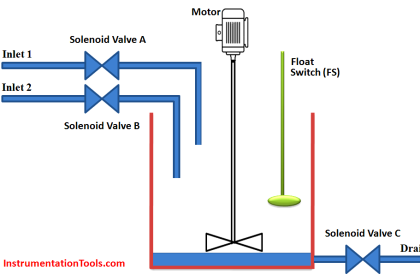
When I have a motor to be controlled with a safety circuit, I usually control this motor with the safety output module through the use of a power contactor; feedback monitoring is used to ensure that the power contactors controlled by the safety output module are able to interrupt the safety circuit. That simply meant the safety PLC will monitor the health of the power contactor to make sure there is no internal fault in the contactor that can affect the safety function if at any time the motor should be stopped.
That means, if there is a welding contact inside the power contactor, the safety circuit should detect that and activate the safety function.
A feedback monitoring instruction is used for that goal. If the power contactor is found to have an unsafe state, such as welded contacts or wiring problems, the safety PLC will give an error and activate the safety function.
How does Feedback Monitoring Work in Safety PLC?
At first startup, the safety PLC will check the if power contactor can be de-energized when the safety function is triggered, it will do that by monitoring the status of two normally closed contacts (NC) of the power contactors.
The NC contacts are guided by the normally open contacts (NO), and they also are mechanically interlocked, which means the NO and NC contacts can never be closed simultaneously unless there is a welded contact in either of them.
When the safety PLC output for the motor is OFF, the motor should be OFF and so the power contactor should also be open, which means the NC contacts should be closed, the Feedback Monitoring function will check the status of the NC contact to ensure proper operation of the power contactor.
If the NC contacts are found to be closed, then contactor is healthy and a safety function can be obtained, but if one of the NC contacts is found to be open, it will mean an internal failure in the contactor has occurred, possibly a welded contact.
Alternatively, if the safety PLC output for the motor is ON, that power contactor should be closed, and that means the NC contacts should be open, and the feedback signal should be zero, if otherwise occurred, it will mean an internal failure in the contactor.
In either case, the safety PLC will react by activating the safety function and preventing the motor from starting from the beginning. Feedback monitoring can be done by either one-channel monitoring or two-channel monitoring.
One-channel monitoring will use two NC contacts connected in series as the feedback signal; this configuration will be able to detect any malfunction in the operation of the contacts.
Two-channel monitoring will also use two NC contacts but they will be wired separately to two different channels in the safety PLC, both NC contacts must be closed within a predefined discrepancy time. This configuration will be able to detect any malfunction in the operation of the contacts, but it will also be able to detect a malfunction in the safety circuit wiring. See the following picture.
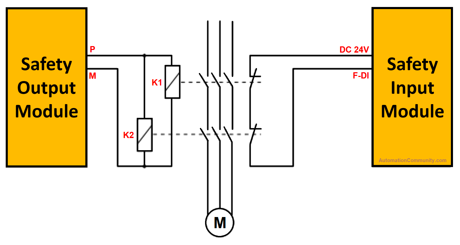
Picture .1 connection of feedback monitoring safety circuit.
The Normal Sequence of the Feedback Function
At start-up, when the output is off: see the next picture.
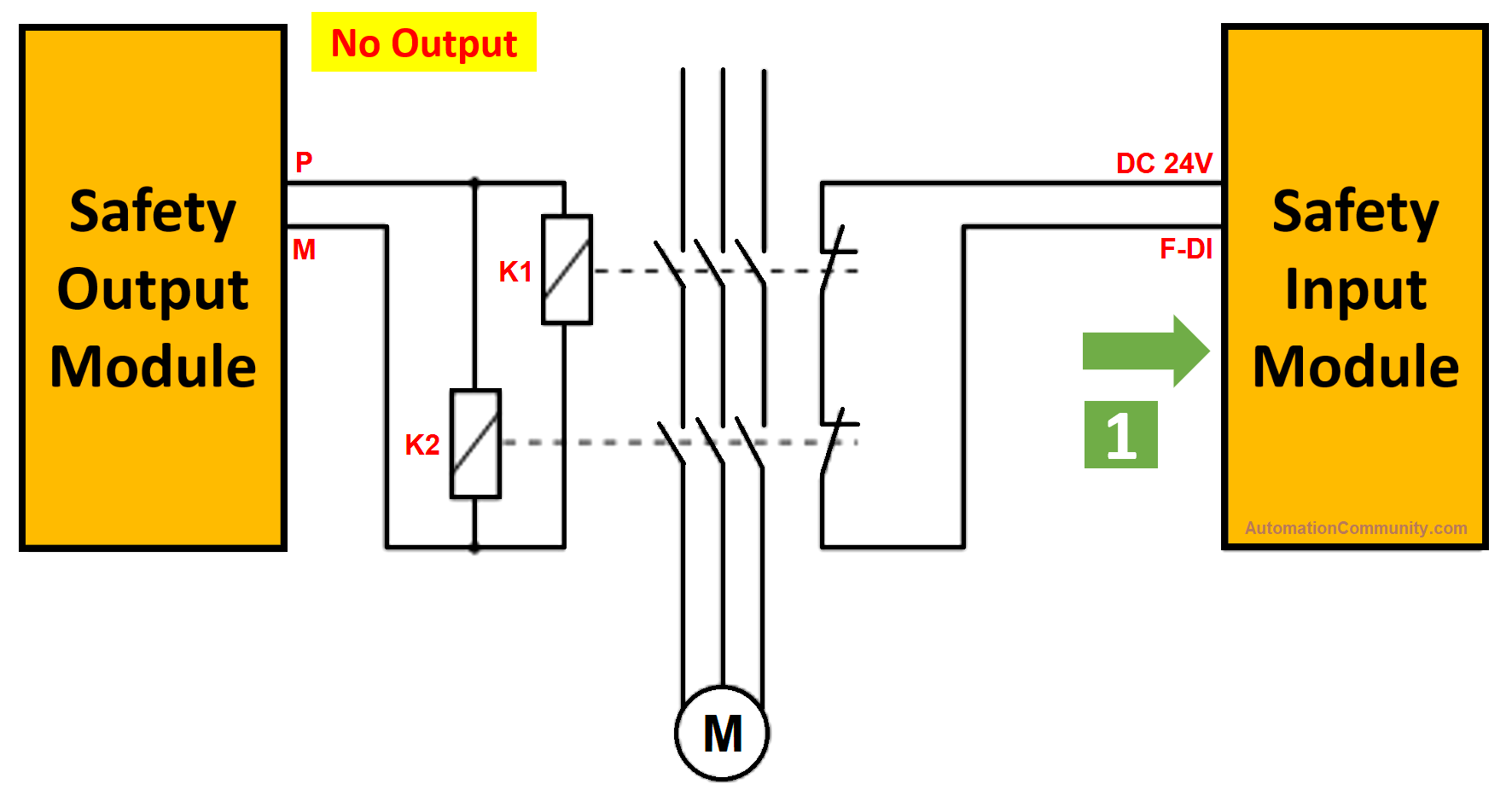
When the contactor is de-energized the feedback signal is 1 as long as there is no internal fault.
When the output is ON, see the next picture
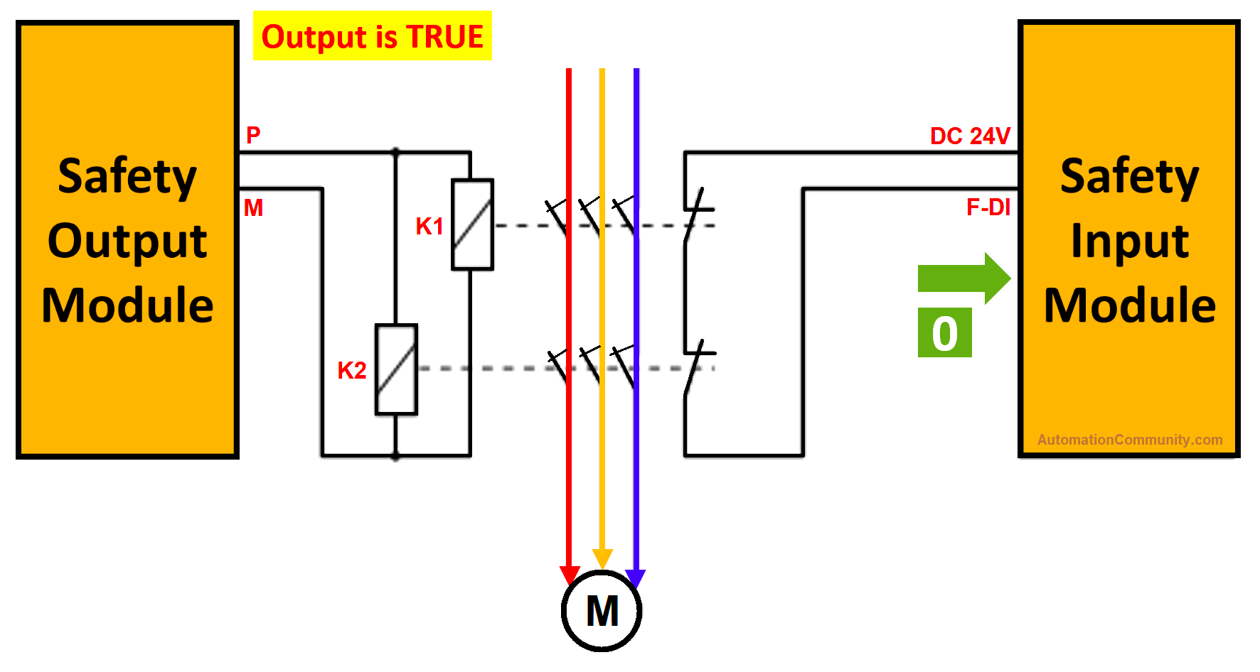
When the output is set to be ON, the power contactor will energize and the feedback signal will be 0.
Simple Program Coding
Hardware configurations:
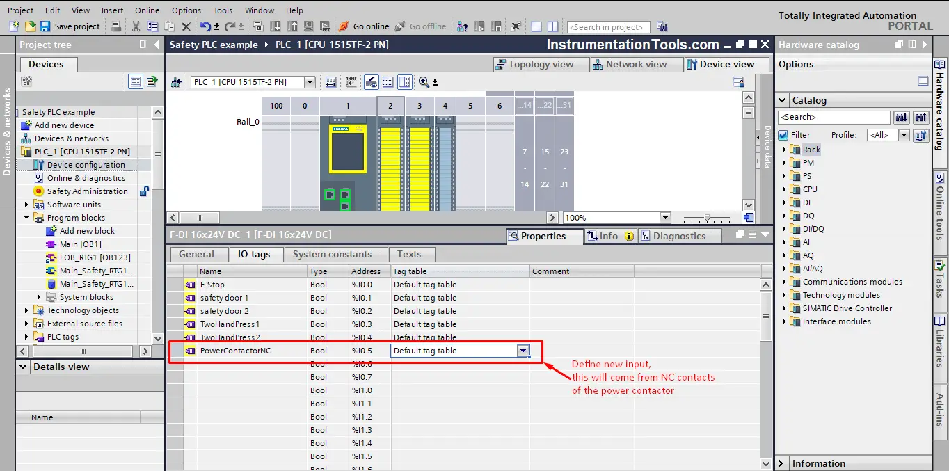
First, define new safety input for the feedback from the power contactor, let’s call it PowerContactorNC.
This bit will be true when the contactor is de-energized and false when the contactor is energized, provided that there is no internal failure in the contactor. See picture 4.
Next, define a safety output that will be responsible for energizing the power contactor, let’s call it EnergizePowerContactor, see picture 5.
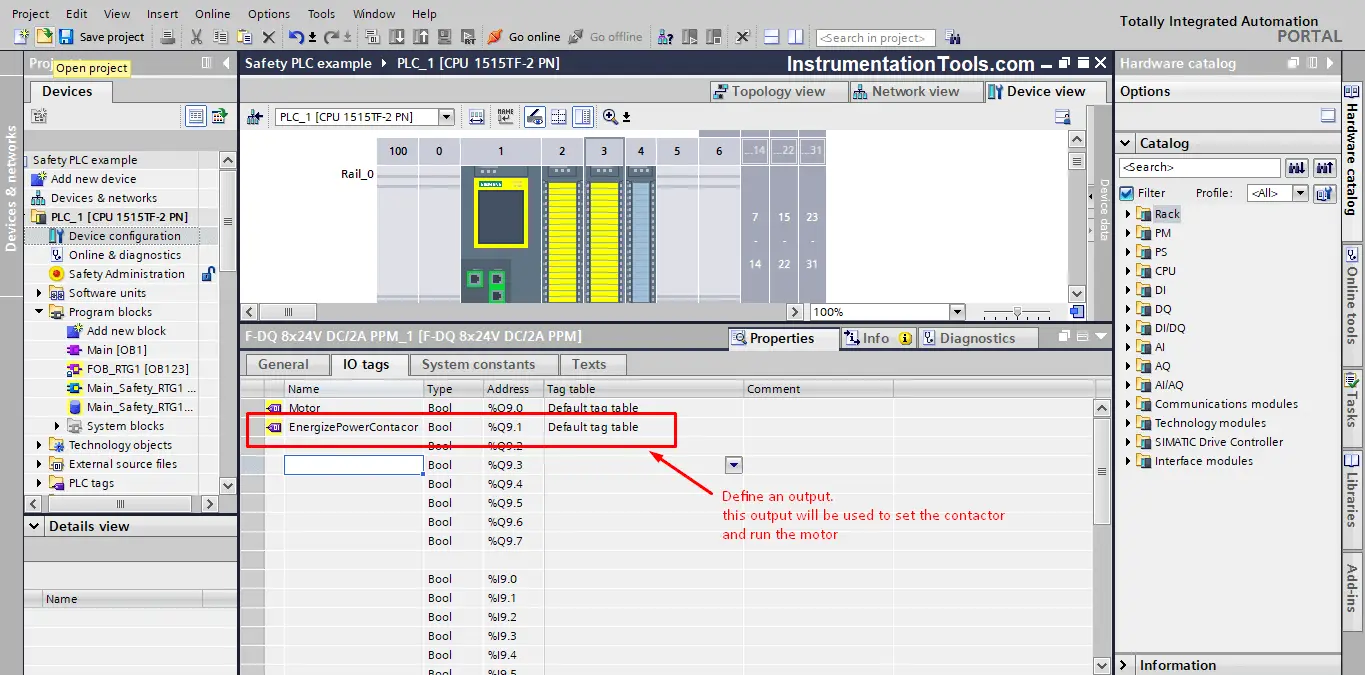
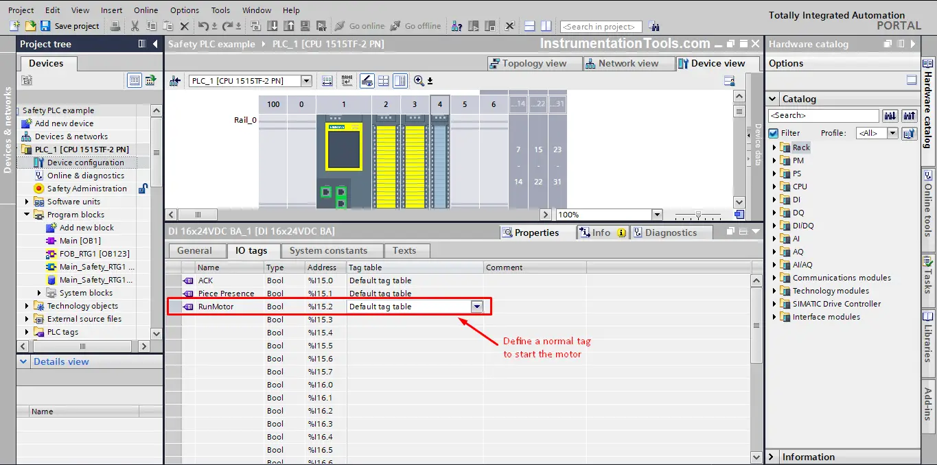
Now, define a normal input to be used to energize the safety output.
Let’s call it RunMotor. This input will set the EnergizePowerContactor to TRUE. See picture 6.
Programming Steps
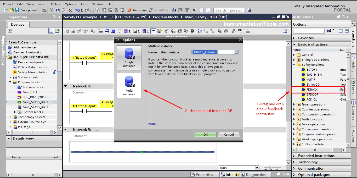
First, add a feedback safety instruction FDBACK and set the call option as Multi-instance DB as usual do. See picture 7.
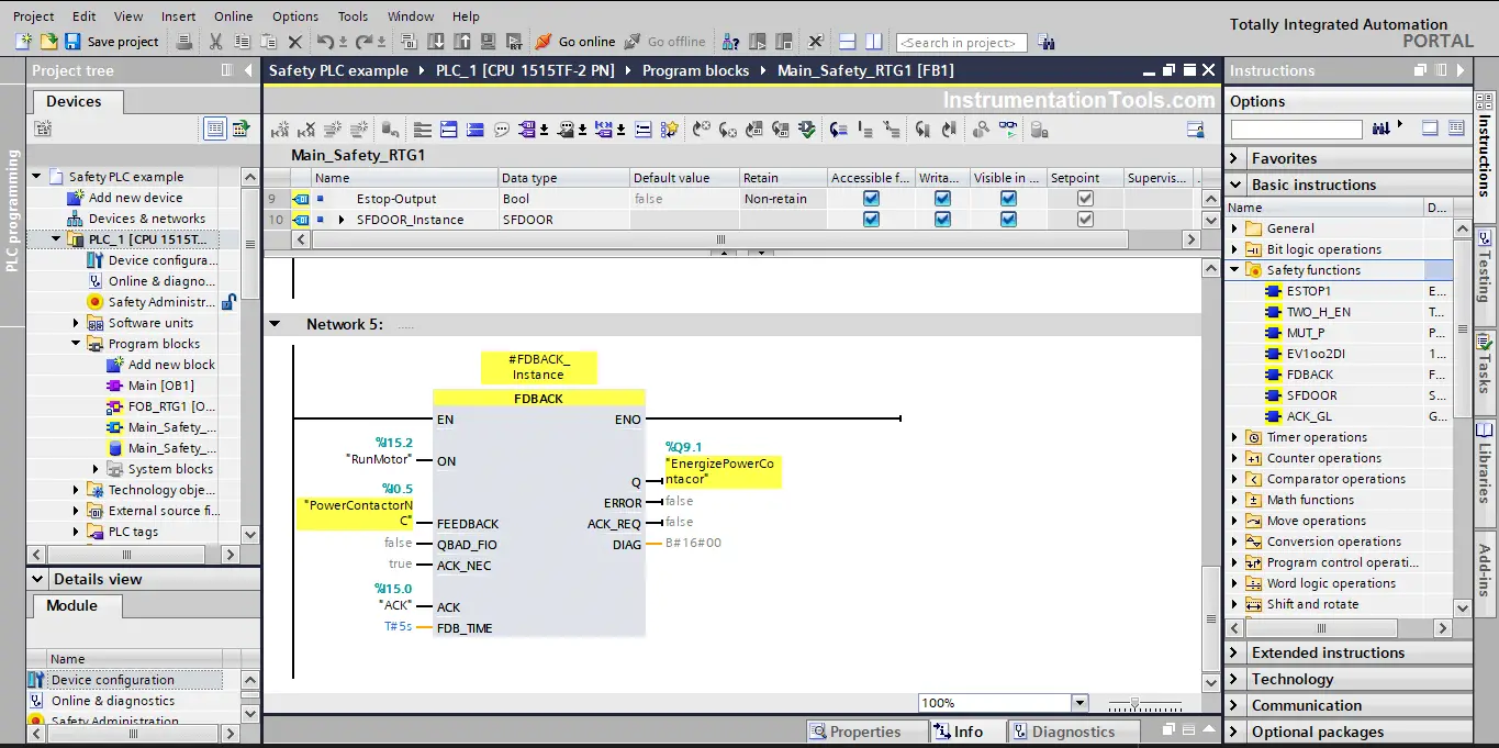
Next, add your inputs and outputs to the FDBACK instruction. For simulation purposes, we will set the feedback time FDB_TIME to 5 seconds. See picture 8.
Code Simulation
Compile your code then start a simulation, notice the following at the beginning
- Output is OFF, which is normal as we didn’t press RunMotor.
- PowerContactorNC is false, it should be true as the contactor is not energized, but this is a simulation, so we need to manually activate this bit.
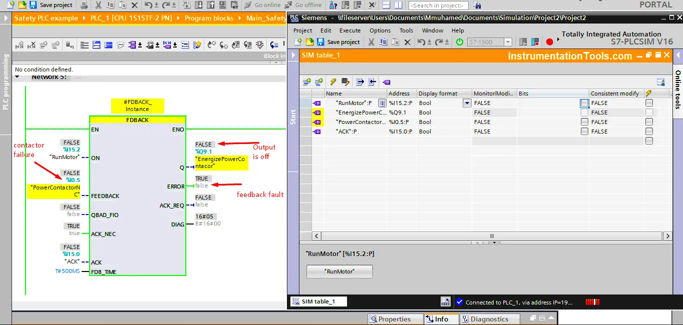
- The FDBACK ERROR bit is giving TRUE, which is normal because the contactor is de-energized and yet, the PowerContactorNC is false. See picture 9.
Now, we will start the simulation of normal conditions.
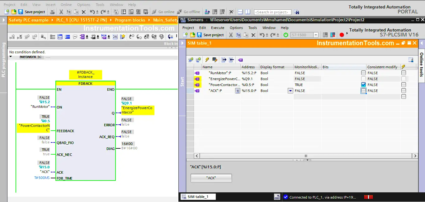
At the start, the motor should be OFF waiting for the RunMotor signal and that means the power contactor should be de-energized and the normally closed contact should be closed, meaning the PowerContactorNC should be TRUE.
Set the PowerContactorNC to TRUE from the simulation. And don’t forget to acknowledge the safety condition by momentarily activating the ACK input. This way the ERROR signal should turn false. See picture 10.
Simulation Points
For the rest of the simulation, see the following animation and notice the following points.
- At the beginning of the video, you will see the last case we mentioned at the previous point, which is the same as picture 10.
- After that, you will see that the RunMotor was pressed, and the output EnergizePowerContactor is immediately ON. Notice that the PowerContactorNC is still true, in real life this would turn false, as the contactor will get energized.
- After the feedback time (5 seconds) has elapsed, the Output EnergizePowerContactor will turn OFF and the FDBACK will give an ERROR. This happened because the PowerContactorNC didn’t turn to false within the 5 seconds, which gave the indication that the contactor might be faulted and that energized the safety circuit.
- Next in the video, you will see that we restored the normal conditions and acknowledge the safety instruction once again, and this time we started the correct procedure of the FDBACK instruction.
- The correct operation is that, PowerContactorNC should be true at the start and once the RunMotor is pressed and the EnergizePowerContactor is TRUE, the PowerContactorNC should become FALSE. If that happens within the allowed 5 seconds, then no errors are given and the output will continue to be TRUE.
- Next in the video, you will see a simulation of what will happen if the contactor fails during operation if the normally closed contact of the power contactor turns TRUE. While the contactor is still energized, the FDBACK will start counting the 5 seconds and if this case still exists, the FDBACK will give an ERROR and the output will stop immediately, even if the RunMotor is still pressed.
- Even if the PowerContactorNC becomes FALSE, the output will not be ON, unless all safety conditions are restored and acknowledged.
Finally, open the attached code yourself and try to experiment with this block to see if you understand how it works or not.
Download the Safety PLC feedback monitoring logic in PDF format and the project back up in the Siemens TIA portal.
P.S. the password for the PLC safety logic is 123
Conclusion
The feedback Monitoring safety function is used to ensure that your safety circuit will be able to stop your process if there is a failure. Monitoring the status of output actuators and comparing them to the required cases enables the safety PLC to detect any failures that can affect the safety of your process.
Again, using a safety PLC has made it very easy to obtain the functionality of the feedback monitoring safety signal, just by drag and drop the pre-defined FDBACK instruction to your code. It would have needed a lot of coding lines to achieve the same functionality if we are using a standard PLC, not to mention we wouldn’t have the redundancy and the diagnoses capabilities of the safety PLC.
If you liked this article, then please subscribe to our YouTube Channel for Instrumentation, Electrical, PLC, and SCADA video tutorials.
You can also follow us on Facebook and Twitter to receive daily updates.
Read Next:
- MOVE Instruction in PLC
- Allen Bradley PLC Hardware
- Motor Classic Control Circuits
- Control System Cyber Security
- How to Design an Effective HMI?


Thank you for great article and explain, this is awesome and very helpful!