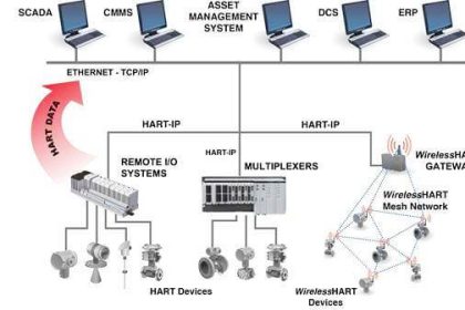
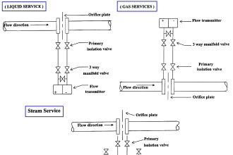
There is usually some freedom of choice in where various function blocks may be located in a FF segment. Take for example the following flow control loop, where a flow transmitter feeds measured flow data into a PID control function block, which then drives a control valve to whatever position necessary to regulate flow. The actual physical device layout might look something like this:
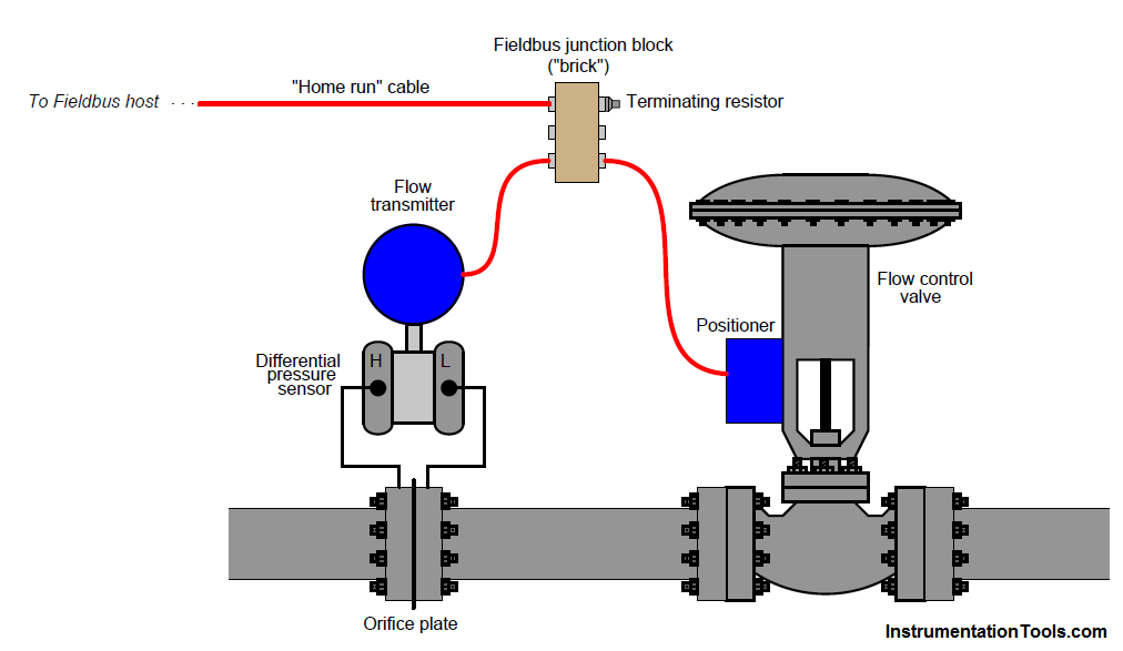
The function block connections necessary for this control scheme to work are shown in the next diagram, coupling the AI (analog input) block located in the transmitter to a PID control block to an AO (analog output) block located in the valve positioner:
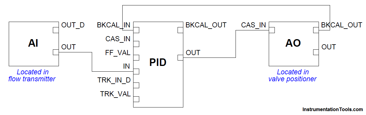
All function block inputs are on the left-hand sides of the blocks, and all outputs are on the right-hand sides. In this function block program, data from the analog input (AI) block flows into the PID block.
After calculating the proper output value, the PID block sends data to the analog output (AO) block where the final control element (e.g. valve, variable-speed motor) is adjusted.
The AO block in turn sends a “back calculation” signal to the PID block to let it know the final control element has successfully reached the state commanded by the PID block’s output.
This is important for the elimination of reset windup in the event the final control element fails to respond to the PID block’s output signal.
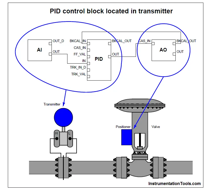
It should be obvious that the analog input (AI) block must reside in the transmitter, simply because only the transmitter is able to measure the process fluid flow rate.
Likewise, it should be obvious that the analog output (AO) block must reside in the control valve positioner, simply because the valve is the only device capable of manipulating (exerting influence over) anything.
However, given the lack of a separate controller device, the person configuring the Fieldbus loop may choose to locate the PID block in either the transmitter or the control valve positioner.
So long as both the FF transmitter and the FF valve positioner possess PID function block capability, it is possible to locate the PID function block in either device.
The following illustrations show the two possible locations of the PID function block in this system:
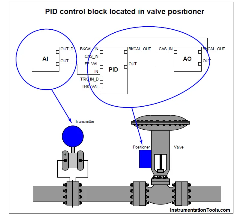
The only factor favoring one location over another for the PID function block is the number of communication broadcasts (“Compel Data” token distributions and replies) necessary per macrocycle.
Note the lines connecting function blocks between the two instruments in the previous diagrams (lines crossing from one blue bubble to another). Each of these lines represents a VCR (Virtual Communication Relationship) – an instance during each macrocycle where data must be transmitted over the network segment from one device to another.
With the PID function block located in the flow transmitter, two lines connect blocks located in different physical devices. With the PID function block located in the valve positioner, only one line connects blocks in different physical devices.
Thus, locating the PID function block in the valve positioner means only one CD message/reply is necessary per macrocycle, making the network communication more efficient.
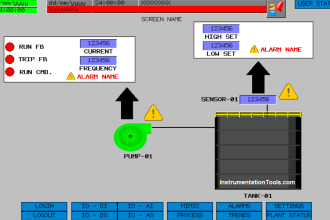
To illustrate the difference this re-location of the PID block makes, we will examine the function block diagram and macrocycle timing schedule on a simple pressure control FF loop, hosted on an Emerson DeltaV distributed control system.
The first composite screenshot shows the function block diagram and schedule with the PID function block located in the transmitter (PT 501):
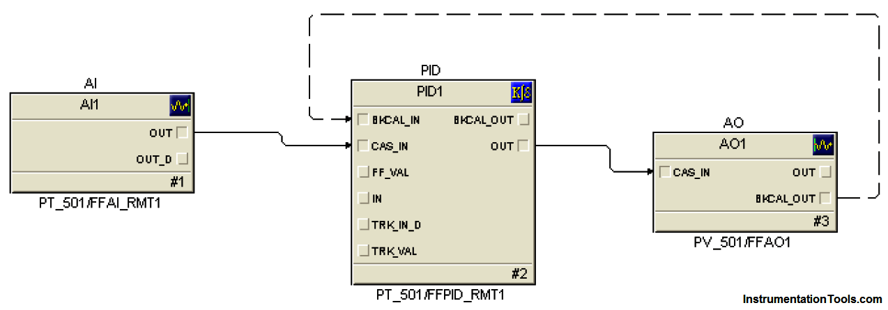
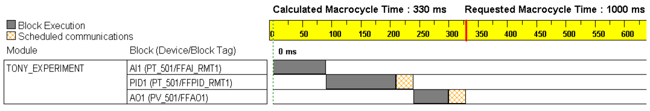
Note the two scheduled communication events (CD tokens and responses) necessary in the macrocycle schedule to enable communication between pressure transmitter PT 501’s PID function block and valve positioner PV 501’s analog output function block.
The first CD token in this macrocycle schedule compels the PID block to publish its “output” signal (subscribed to by the analog output block), while the second token compels the analog output block to publish its “back calculation” signal (subscribed to by the PID block). The amount of time required for function block execution and their publisher/subscriber communications is 330 milliseconds, with a total macrocycle time of 1 second.
Now let’s examine the same PID pressure control system with the PID function block moved to the valve. Here you see the function block diagram followed immediately by the updated macrocycle schedule:
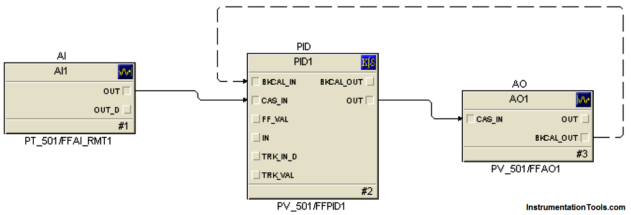
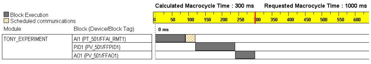
In this macrocycle timing schedule, there is only one CD token needed: compelling the analog input block to publish its measurement signal (subscribed to by the PID block).
This makes the block execution plus scheduled communication time 30 milliseconds shorter than before (300 milliseconds total as opposed to 330 milliseconds), since there is one less scheduled communications event happening.
The total macrocycle time of 1 second remains unchanged, but now we have 30 milliseconds more unscheduled time during which other communication events may take place.