Inst ToolsInst ToolsInst Tools
  • Courses
  • Automation
    • PLC
    • Control System
    • Safety System
    • Communication
    • Fire & Gas System
  • Instrumentation
    • Design
    • Pressure
    • Temperature
    • Flow
    • Level
    • Vibration
    • Analyzer
    • Control Valve
    • Switch
    • Calibration
    • Erection & Commissioning
  • Interview
    • Instrumentation
    • Electrical
    • Electronics
    • Practical
  • Q&A
    • Instrumentation
    • Control System
    • Electrical
    • Electronics
    • Analog Electronics
    • Digital Electronics
    • Power Electronics
    • Microprocessor
  • Request
Search
  • Books
  • Software
  • Projects
  • Process
  • Tools
  • Basics
  • Formula
  • Power Plant
  • Root Cause Analysis
  • Electrical Basics
  • Animation
  • Standards
  • 4-20 mA Course
  • Siemens PLC Course
Reading: What is a Four-wire RTD ?
Share
Notification Show More
Font ResizerAa
Inst ToolsInst Tools
Font ResizerAa
  • Courses
  • Design
  • PLC
  • Interview
  • Control System
Search
  • Courses
  • Automation
    • PLC
    • Control System
    • Safety System
    • Communication
    • Fire & Gas System
  • Instrumentation
    • Design
    • Pressure
    • Temperature
    • Flow
    • Level
    • Vibration
    • Analyzer
    • Control Valve
    • Switch
    • Calibration
    • Erection & Commissioning
  • Interview
    • Instrumentation
    • Electrical
    • Electronics
    • Practical
  • Q&A
    • Instrumentation
    • Control System
    • Electrical
    • Electronics
    • Analog Electronics
    • Digital Electronics
    • Power Electronics
    • Microprocessor
  • Request
Follow US
All rights reserved. Reproduction in whole or in part without written permission is prohibited.
Inst Tools > Blog > Temperature Measurement > What is a Four-wire RTD ?

What is a Four-wire RTD ?

Last updated: November 20, 2019 11:12 am
Editorial Staff
Temperature Measurement
1 Comment
Share
3 Min Read
SHARE

A very old electrical measurement technique known as the Kelvin or four-wire method is a practical solution to the problem of wire resistance.

Commonly employed to make precise resistance measurements for scientific experiments in laboratory conditions, the four-wire technique uses four wires to connect the resistance under test (in this case, the RTD) to the measuring instrument, which consists of a voltmeter and a precision current source.

Two wires carry “excitation” current to the RTD from the current source while the other two wires merely “sense” voltage drop across the RTD resistor element and carry that voltage signal to the voltmeter.

RTD resistance is calculated using Ohm’s Law: taking the measured voltage displayed by the voltmeter and dividing that figure by the regulated current value of the current source.

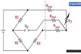
A simple 4-wire RTD circuit is shown here for illustration:

Four Wire RTD Circuit

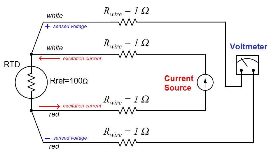
Wire resistances are completely inconsequential in this circuit. The two “excitation” wires carrying current to the RTD will drop some voltage along their length, but this voltage drop is only “seen” by the current source and not the voltmeter.

The two “sense” wires connecting the voltmeter to the RTD also possess resistance, but they drop negligible voltage because the voltmeter draws so little current through them.

Thus, the resistances of the current-carrying wires are of no effect because the voltmeter never senses their voltage drops, and the resistances of the voltmeter’s sensing wires are of no effect because they carry practically zero current.

Note how wire colors (white and red) indicate which wires are common pairs at the RTD. The RTD is polarity-insensitive because it is nothing more than a resistor, which is why it doesn’t matter which color is positive and which color is negative.

The only disadvantage of the four-wire method is the sheer number of wires necessary. Four wires per RTD can add up to a sizeable wire count when many different RTDs are installed in a process area.

Also Read : RTD Standards

Credits : Tony R. Kuphaldt – Creative Commons Attribution 4.0 License

Don't Miss Our Updates
Be the first to get exclusive content straight to your email.
We promise not to spam you. You can unsubscribe at any time.
Invalid email address
You've successfully subscribed !

Continue Reading

Temperature Error of 2-Wire, 3-Wire & 4-Wire RTD
Temperature Switch Working Principle
Types of Thermowells
How Does an Infrared Thermometer Work?
What is a Thermocouple ?
What is a Thermopile ?
Share This Article
Facebook Whatsapp Whatsapp LinkedIn Copy Link
Share
1 Comment
  • Siddhartha Kumar Maiti says:
    December 20, 2017 at 9:15 am

    Sir, a pressure transmitter of Honeywell shows error Pu comm failed. Sir I can’t understand what is the problem?

    Reply

Leave a Reply Cancel reply

Your email address will not be published. Required fields are marked *

Stay Connected

128.3kFollowersLike
69.1kFollowersFollow
210kSubscribersSubscribe
38kFollowersFollow

Categories

Explore More

Bimetallic Thermometer
RTD Wheatstone Bridge Circuits
Difference Between 2 wire RTD, 3 wire RTD, and 4 wire RTD’s
Why we use Wheatstone bridge in RTD?
Difference between PT100, PT1000, Nickel RTD and Balco RTD
Temperature Sensors Questions & Answers
Introduction to RTDs
RTD Questions and Answers

Keep Learning

Thermocouple Types

Types of Thermocouples

Measuring temperature with RTD

How RTD Measuring the Temperature

Temperature Coefficient of Resistance

Temperature Coefficient of Resistance (α)

Thermocouple Law of Intermediate Metals

Thermocouples Law of Intermediate Metals

Disadvantages of Resistance Temperature Detectors (RTD)

Disadvantages of Resistance Temperature Detectors

Liquid In Glass Thermometers

Liquid In Glass Thermometer Principle

Functions of Temperature Detectors

Functions of Temperature Detectors

Pressure and Temperature Gauges

Pressure and Temperature Gauges

Learn More

Voltage Polarities

Voltage Polarity and Current Direction

3-way-2-position-solenoid-valve-spring-return

Pneumatic Directional Control Valves

Hydrogen sulfide gas

Hydrogen Sulfide Gas (H2S)

Capacitor Bank

Poor Power Factor Boosted – Industrial Electrical Problems

Electric Circuits Objective Questions

Electric Circuits Objective Questions – Set 16

Magnetic proximity sensors

Magnetic Proximity Detectors – Types, Principle, Advantages

Potential Difference Across a Conductor Causes a Current to Flow

Conductor, Insulator, Resistor and Current Flow

Optimal Control Systems

Parameter Optimization : Servomechanims

Menu

  • About
  • Privacy Policy
  • Copyright

Quick Links

  • Learn PLC
  • Helping Hand
  • Part Time Job

YouTube Subscribe

Follow US
All rights reserved. Reproduction in whole or in part without written permission is prohibited.
Welcome Back!

Sign in to your account

Username or Email Address
Password

Lost your password?