Inst ToolsInst ToolsInst Tools
  • Courses
  • Automation
    • PLC
    • Control System
    • Safety System
    • Communication
    • Fire & Gas System
  • Instrumentation
    • Design
    • Pressure
    • Temperature
    • Flow
    • Level
    • Vibration
    • Analyzer
    • Control Valve
    • Switch
    • Calibration
    • Erection & Commissioning
  • Interview
    • Instrumentation
    • Electrical
    • Electronics
    • Practical
  • Q&A
    • Instrumentation
    • Control System
    • Electrical
    • Electronics
    • Analog Electronics
    • Digital Electronics
    • Power Electronics
    • Microprocessor
  • Request
Search
  • Books
  • Software
  • Projects
  • Process
  • Tools
  • Basics
  • Formula
  • Power Plant
  • Root Cause Analysis
  • Electrical Basics
  • Animation
  • Standards
  • 4-20 mA Course
  • Siemens PLC Course
Reading: 4-wire Transmitters Current Loops
Share
Notification Show More
Font ResizerAa
Inst ToolsInst Tools
Font ResizerAa
  • Courses
  • Design
  • PLC
  • Interview
  • Control System
Search
  • Courses
  • Automation
    • PLC
    • Control System
    • Safety System
    • Communication
    • Fire & Gas System
  • Instrumentation
    • Design
    • Pressure
    • Temperature
    • Flow
    • Level
    • Vibration
    • Analyzer
    • Control Valve
    • Switch
    • Calibration
    • Erection & Commissioning
  • Interview
    • Instrumentation
    • Electrical
    • Electronics
    • Practical
  • Q&A
    • Instrumentation
    • Control System
    • Electrical
    • Electronics
    • Analog Electronics
    • Digital Electronics
    • Power Electronics
    • Microprocessor
  • Request
Follow US
All rights reserved. Reproduction in whole or in part without written permission is prohibited.
Inst Tools > Blog > Common > 4-wire Transmitters Current Loops

4-wire Transmitters Current Loops

Last updated: March 16, 2020 5:16 pm
Editorial Staff
Common Control Systems
1 Comment
Share
3 Min Read
SHARE

4-wire (“self-powered”) Transmitter current loops

DC electric current signals may also be used to communicate process measurement information from transmitters to controllers (PLC/DCS), indicators, recorders, alarms, and other input devices. Recall that the purpose of a transmitter is to sense some physical variable (e.g. pressure, temperature, flow) and then report that quantity in the form of a signal, in this case a 4 to 20 milliamp DC current proportional to that measured quantity.

The simplest form of 4-20 mA measurement loop is one where the transmitter has two terminals for the 4-20 mA signal wires to connect, and two more terminals where a power source connects. These transmitters are called “4-wire” or “self-powered” units. The current signal from the transmitter connects to the process variable input terminals of the controller to complete the loop:

Note :

  • Here in this article, we are assuming a simple microcontrollers based controllers is connected with a 4 wire transmitters.
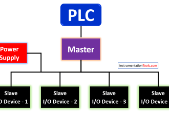
  • For a PLC/DCS systems, the standard resistor & Analog to Digital Converters (ADC) are found in Analog Input (AI) Cards.

4 wire transmitter current loops

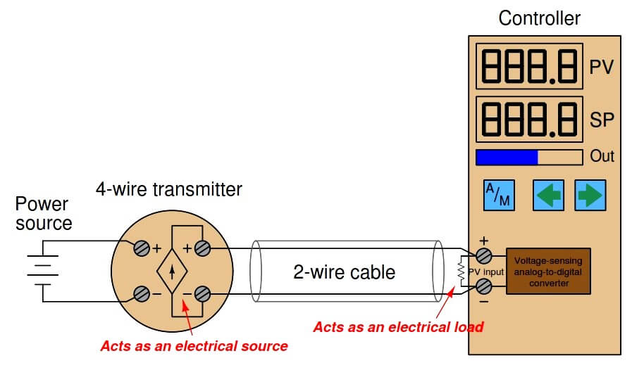
Some process controllers are not equipped to directly accept milliamp input signals, but rather can only interpret DC voltage signals. In such cases we must connect a precision resistor across the controller’s input terminals to convert the 4-20 mA transmitter signal into a standardized analog voltage signal the controller can understand.

A voltage signal range of 1 to 5 volts is standard, although some models of controller use different voltage ranges and therefore require different precision resistor values. If the voltage range is 1-5 volts and the current range is 4-20 mA, the precision resistor value must be 250 ohms according to Ohm’s Law.

Since this is a digital controller, the input voltage at the controller terminals is interpreted by an analog-to-digital converter (ADC) circuit, which converts the measured voltage into a digital number the controller’s microprocessor can interpret.

In some installations, transmitter power is supplied through additional wires in the cable from a power source located near the controller:

Four Wire Current Loop

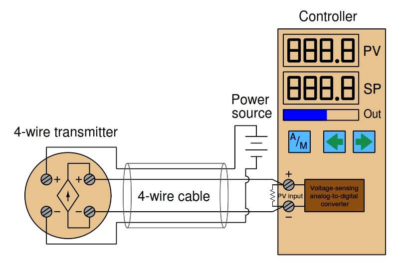
The obvious disadvantage of this scheme is the requirement of two more conductors in the cable. More conductors means the cable will be larger-diameter and more expensive for a given length. Cables with more conductors will require larger electrical conduit to fit in to, and all field wiring panels will have to contain more terminal blocks to marshal the additional conductors. If no suitable electrical power source exists at the transmitter location, though, a 4-wire cable is necessary to service a 4-wire transmitter.

Credits : by Tony R. Kuphaldt – Creative Commons Attribution 4.0 License

Don't Miss Our Updates
Be the first to get exclusive content straight to your email.
We promise not to spam you. You can unsubscribe at any time.
Invalid email address
You've successfully subscribed !

Continue Reading

Modbus Relative Addressing
5 Ways CNC Machining is Benefiting the Glass Industry
Loop Calibrator to Simulate a 4-20 mA Signal
Node-RED in PLC Industrial Automation
What is Instrument Hook Up Diagram ?
Classification of Weighing Balance and Weight
Share This Article
Facebook Whatsapp Whatsapp LinkedIn Copy Link
Share
1 Comment
  • Kanterson says:
    July 6, 2019 at 11:48 am

    4-wired transmitters here the 4 wires means 2 wires for analog signal (normally 4~20 mA) and 2 wires for pure power supply.

    4-wired transmitters need much higher working voltage and working current to satisfy the device functionality (compare with 2-wired loop powered transmitters).

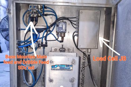
    Typical 4-wired transmitters in the market are: Coriolis Mass Flow Transmitter, Ultrasonic Flow Transmitter, Electromagnetic Flow Transmitter, etc.

    The power supply request have two versions, i.e., DC and AC, but most popular is the AC version since there is normally no voltage drop issue.

    Additional power cable pulling from power distribution cabinet to field transmitter have to be considered during engineering phase.

    Currently, maybe you only can find the 4-wired transmitters in the market but instrument vendor product development target is to develop the 2-wired version eventually in the future. The 2-wired version is less complexity on wiring issue and likely by instrument engineers.

    Reply

Leave a Reply Cancel reply

Your email address will not be published. Required fields are marked *

Stay Connected

128.3kFollowersLike
69.1kFollowersFollow
210kSubscribersSubscribe
38kFollowersFollow

Categories

Explore More

How to Do Linear Programming in Excel?
What is a Displacement Transducer? – Types and Advantages
Measurement Unit Conversions
2-wire Transmitters Current Loops
What is an Automotive Radiator?
De-energize to Safe Loop philosophy
All About Electric Motors and Universal Motors
Ratio Controller Example

Keep Learning

DeviceNet

What is DeviceNet?

How To Choose A Surge Protector?

How To Choose A Surge Protector?

Voting System in PLC

Voting Concept in Package Safety System

Advantages of Industrial Automation

Advantages and Disadvantages of Industrial Automation

Difference Between CNC Machine and VMC Machine

Difference Between CNC Machine and VMC Machine

Industrial Automation Solution

How to Choose the Right Industrial Automation Solution?

Metric Prefixes and Unit Conversions

Metric Prefixes and Unit Conversions

Difference between Feedback, Feedforward, and Cascade Control

Difference between Feedback, Feedforward, and Cascade Control?

Learn More

Connection between PLC and Contactor

Contactor – Basics, Wiring, Connection with PLC

Phase Failure Relay

Why is Phase Failure Relay Required in LV Panels?

RTD Connection Diagram

Difference Between 2 wire RTD, 3 wire RTD, and 4 wire RTD’s

PID block from the PLC library

How to Configure PID Controller in Various Schneider PLCs?

Electric Circuits Objective Questions

Electric Circuits Objective Questions – Set 8

Squirrel Cage Induction Motor vs Slip Ring Induction Motor

Installation and Calibration of Pressure Transmitter

Installation and Calibration of Pressure Transmitter

heated instrument enclosures

What is Instrument Heated Enclosure or Protection Box?

Menu

  • About
  • Privacy Policy
  • Copyright

Quick Links

  • Learn PLC
  • Helping Hand
  • Part Time Job

YouTube Subscribe

Follow US
All rights reserved. Reproduction in whole or in part without written permission is prohibited.
Welcome Back!

Sign in to your account

Username or Email Address
Password

Lost your password?