A formal definition of a ground loop that is very general is provided in IEEE Std. 100-1991, IEEE Dictionary as follows: . . . a ground loop is “formed when two or more points in an electrical system that are nominally at ground potential are connected by a conducting path such that either or both points are not at the same potential.” While this is a good general purpose definition, it is not sufficiently specific for use when dealing with signal level circuits and grounding connections. Therefore, a more specific and useful definition as provided in this document is as follows:
Ground Loop (unwanted)
Any conductive path involving “ground” via a grounding or grounded conductor or the earth itself, through which any part or all of the desired signal process current is passed, so that it may be algebraically added to any unwanted current such as “noise” that may also be flowing in the shared ground path.
Ground Loop (desired)
Any number of paralleled conductors and connections involving grounded or grounding conductors of any description, or the earth, and through which it is intended to conduct ac system ground fault or lightning currents, for the purpose of reducing arcing, touch potential hazards, and as an aid to fault clearing.
Ground Loop (benign)
Either of the above two ground loops or a combination of them, where despite the existence of the ground loop, no electrical hazards are created and no signal processes are disrupted, by its existence.
Since we are concerned with the unwanted effects of ground loops on signals, we will mainly use the first of the above definitions.

Signals which are transmitted on isolated balanced pairs are not referenced to ground, and differentially coupled signals that are referenced to ground are relatively immune to problems involving the ground reference to which they are connected.
With these circuits we are only concerned with voltages to ground that are high enough to cause voltage breakdown of insulation systems or electronic components, or to saturate the magnetics that may be used to isolate and couple the signal between the signal cable and the electronics used to drive or receive the signal on the path.
Unbalanced signals referenced to ground fall into two general categories:
- There are those that typically employ coaxial cable with only one center conductor for the signal transport process and where the outer braid is grounded at both ends. This includes many kinds of circuits used with computers, process control systems, and similar installations.
- There are those that use a common conductor which is grounded, as a part of the signal return path for one or more signals on a multi-conductor cable. Standard signal protocol, RS-232 usually falls into this category.
In both of the above examples, if unwanted current flow is caused in the grounded conductor that also carries signal, and if there is an overlap between the bandwidth of the interfering signal and the desired one, then the signal process is almost certain to be disrupted once the interference reaches a minimum level of amplitude.
Two principle means of dealing with the above ground loop problem generally exist as follows:
(1) Change the signal’s protocol using a converter, to one that does not use the “ground” path for any of the signal current, or;
(2) Shunt the ends of the cable involved in the ground loop by effectively bonding the equipment at each end of the cable to the same SRG. This greatly reduces the effects of the noise current in the signal conductor path by providing a myriad of parallel paths for it to flow in via the low impedance SRG.
However, the desired signal will still stay relatively evenly divided between the two signal conductors on the cable and not flow into the SRG. This occurs because the mutually coupled fields from the closely coupled supply and return conductors in the cable and for the signal, act to make this path a much lower impedance for the signal currents to travel in than the SRG.
Our recommendation is to properly design and implement the facility’s grounding system to avoid its unwanted involvement with the operation of the equipment. This kind of approach can also eliminate the need to consider equipment modifications and to engage in costly diagnostic efforts since most trouble involving common-mode noise is avoided in the signal circuits. A properly installed SRG along with good bonding practices is a recommended method of minimizing common-mode noise problems, so it becomes a first-line of defense in such cases.
While it may be true that an SRG based design of this kind is both conservative and somewhat more costly (initially) than other wiring techniques that are commonly used, our experience clearly shows that using the SRG approach produces superior and ultimately, more cost-effective results due to the lack of later operational problems. In other words, a conservative design involving an SRG costs a little more, but avoids lots of very difficult and potentially expensive problems after the job is done.

How to Solve Electrical Ground Loop Problems?
It is generally not possible in complex systems with interconnected data and signal conductors to avoid all ground loops.
Some approaches that may be used to avoid the detrimental effects of such ground loops include:
Point #1
Where possible, cluster the interconnected electronic equipment into an area that is served by a single signal reference grid (SRG). If the interconnected equipment is located in separate, but adjacent rooms, then a common signal reference grid should serve all the rooms.
Point #2
Effectively bond each frame/enclosure of the interconnected equipment to the SRG. In this way, the SRG acts like a uniformly shared ground reference that maintains a usefully low impedance over a very broad range of frequency. Typically, from dc to several tens of MHz, for example.
Point #3
Where a work area exists and its PC is connected to a network, keep all of the work area’s equipment (e.g., CPU, monitor, printer, external modem, etc.) closely clustered and powered by a work area dedicated branch circuit. If it is required to use more than one branch circuit for the work area’s power, be sure that both are powered from the same panelboard. Avoid connecting any other equipment to the branch circuit(s) used by the work area’s equipment.
Point #4
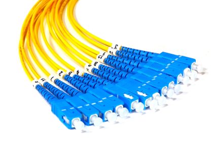
Use fiber optical paths for data circuits. The best, but also the most expensive solution is to use fiber optical cables for all data circuits since there can be no ground loops with these kinds of circuits (or surge current problems).
However, due to increased initial cost and added complexity, the use of fiber optic cable circuits is usually (and unfortunately) viewed as a last resort. Instead, it should be viewed as an important first strategy that avoids problems that may ultimately cost more to resolve.
Point #5
Use opto-isolators which can provide several kV of isolation for the data path that they are used on. These are available as add-on data transmission protocol converters for most popular forms of data circuits.
This is a very useful retrofit option for data circuits being affected by surges and ground loops. Surge protection devices (SPD) are also recommended to be applied to these circuits if protection from the higher voltages associated with larger currents is needed.
Point #6
Other forms of protocol converters can be applied to standard forms of signal circuits to make them less susceptible to common-mode noise on grounding conductors associated with the signal path. For example, a conversion from RS-232 to RS-422 or RS-485, etc. should be considered in especially noisy environments.
Point #7
Improve the shielding provided for the data signal cables. Place the cables into well and frequently grounded metal conduits or similar raceways.
Point #8
Follow the recommendations for installing signal cables in IEEE Std. 1100, Recommended Practice for Powering and Grounding Sensitive Electronic Equipment.
Equipment interconnected by data signal cables and located on different floors or that is widely separated in a building, may not be able to effectively use some or all of the above solutions, except those involving optical isolation and certain of the protocol conversion techniques. This occurs since the terminating equipment for the signal cables is likely to be powered from different branch circuits, panelboards, and even separately derived ac systems. Therefore, the associated equipment ground references are likely to be at different potential at least some of the time.
While the best solution to the above situation involves either fiber optic or opto-isolation techniques, it is often possible to achieve good performance by providing each of the separate locations with an SRG, and then interconnecting the SRGs with widely spaced apart and multiple grounding/bonding conductors, solid-bottom metal cable trays, wireways, or conduits containing the data signal cables.
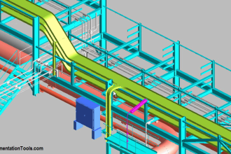
An example of using widely spaced grounding/bonding conductors to interconnect two SRG areas is when there is structural building steel available and when it can be used in this role.
Since structural steel columns are installed on standard spacings in a given building, these columns can typically be used for the purpose. Wide spacing is necessary since the conductors involved are inductors and the mutual inductance between such conductors that are not widely spaced, is quite high. This makes several closely spaced conductors appear as a single inductor and not as paralleled inductances, which exhibit lower overall reactance between the items they are being used to interconnect.
Also, each of the above separated equipment areas containing SRGs should be ac powered from a locally installed and SRG referenced isolation transformer as opposed to them being powered from panelboards and feeders from some remotely located power source.
Finally, since separated areas in a building are subject to large potential differences due to lightning discharge currents and some forms of ac system ground faults, the ends of the signal cables should always be equipped with surge protection devices (SPDs).
Do you face any problems with grounding? Share with us.
Reference: erico
If you liked this article, then please subscribe to our YouTube Channel for PLC and SCADA video tutorials.
You can also follow us on Facebook and Twitter to receive daily updates.
Read Next:
- Importance of Grounding System
- What is a Ground Detector?
- Neutral Grounding in Power System
- Step and Touch Potential in Ground
- Cable Fault Identification Methods