In this article, you will learn the Modbus Function Codes like Read and write of coil, contact, holding register, and analog input register, etc.
Every Modbus data frame, whether ASCII or RTU mode, has a field designated for “data.” For each Modbus function, the content of this “data” field follows a specific format. It is the purpose of this subsection to document the data formats required for common Modbus functions, both the “Query” message transmitted by the Modbus master device to a slave device and the corresponding “Response” message transmitted back to the master device by the queried slave device.
Since each Modbus data frame is packaged in multiples of 8 bits (RTU), they are usually represented in text as individual bytes (two hexadecimal characters).
For example, a 16-bit “word” of Modbus data such as 1100100101011011 would typically be documented as C9 5B with a deliberate space separating the “Hi” (C9) and “Lo” (5B) bytes.
The fact that all Modbus words appear in this order means that Modbus follows the “big-endian” standard.
Modbus Function Code 01 – Read Coil
This Modbus function reads the statuses of slave device discrete outputs (“coils”) within the slave device, returning those statuses in blocks of eight (even if the “number of coils” specified in the query is not a multiple of eight!).
Relevant Modbus addresses for this function range from 00001 to 09999 (decimal) but the starting address is a hexadecimal number representing the (n -1)th register from the beginning of this range (e.g. absolute decimal address 00100 would be specified as hexadecimal 0x0063, as a high-order byte 00 immediately followed by a low-order byte 63).
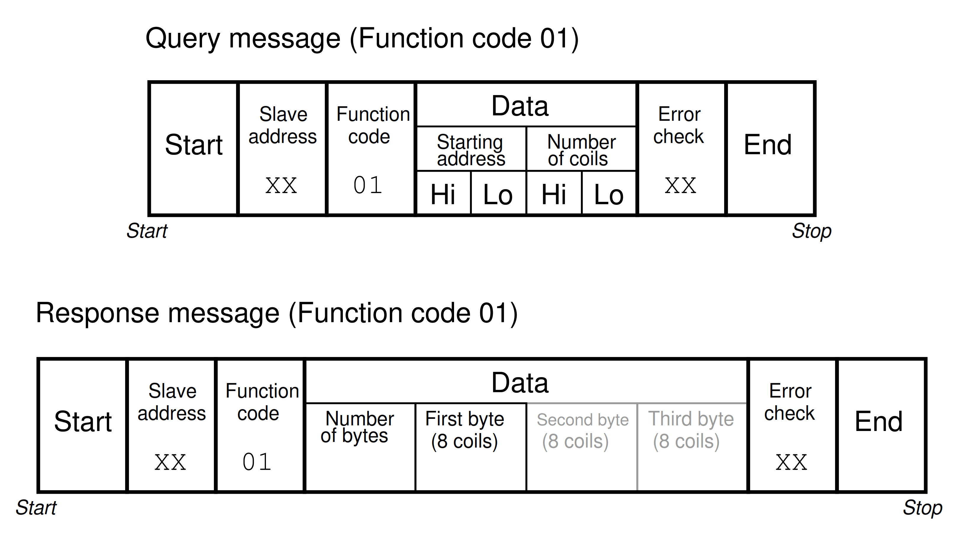
Note that the second and third bytes representing coil status are shown in grey, because their existence assumes more than one byte worth of coils has been requested in the query.
Modbus Function Code 02 – Read Contact
This Modbus function reads the statuses of slave device discrete inputs (“contacts”) within the slave device, returning those statuses in blocks of eight (even if the “number of contacts” specified in the query is not a multiple of eight!).
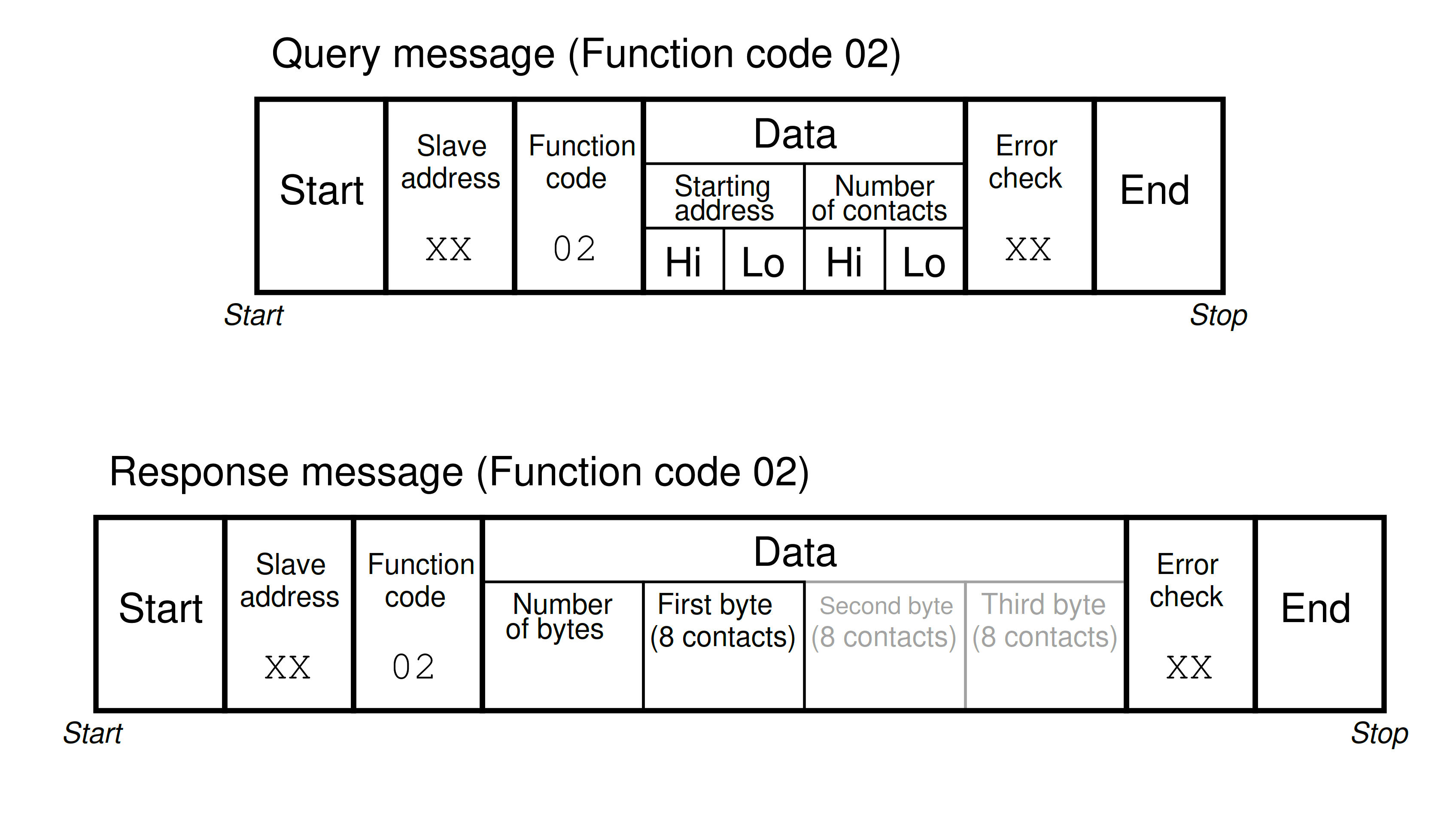
Relevant Modbus addresses for this function range from 10001 to 19999 (decimal), but the starting address is a hexadecimal number representing the (n – 1)th register from the beginning of this range (e.g. absolute decimal address 10256 would be specified as hexadecimal 0x00FF: the “Hi” byte being 00 and the “Lo” byte being FF).
Modbus Function Code 03 – Read Holding Register
This Modbus function reads the statuses of “holding” registers within the slave device, with the size of each register assumed to be two bytes (16 bits).
Relevant Modbus addresses for this function range from 40001 to 49999 (decimal), but the starting address is a hexadecimal number representing the (n -1)th register from the beginning of this range (e.g. absolute decimal address 40980 would be specified as hexadecimal 0x03D3, “Hi” byte 03 and “Lo” byte D3.).

Note that since the query message specifies the number of registers (each register being two bytes in size), and the response message replies with the number of bytes, the response message’s “number of bytes” field will have a value twice that of the query message’s “number of registers” field.
Note also that the maximum number of registers which may be requested in the query message (65536) with “Hi” and “Lo” byte values grossly exceeds the number of bytes the response message can report (255) with its single byte value.
Modbus Function Code 04 – Read Analog Input Register
This Modbus function is virtually identical to 03 (Read Holding Registers) except that it reads “input” registers instead: addresses 30001 through 39999 (decimal).
As with all the Modbus relative addresses, the starting address specified in both messages is a hexadecimal number representing the (n – 1)th register from the beginning of this range (e.g. absolute decimal address 32893 would be specified as hexadecimal 0x0B4C, “Hi” byte 0B followed by “Lo” byte 4C).
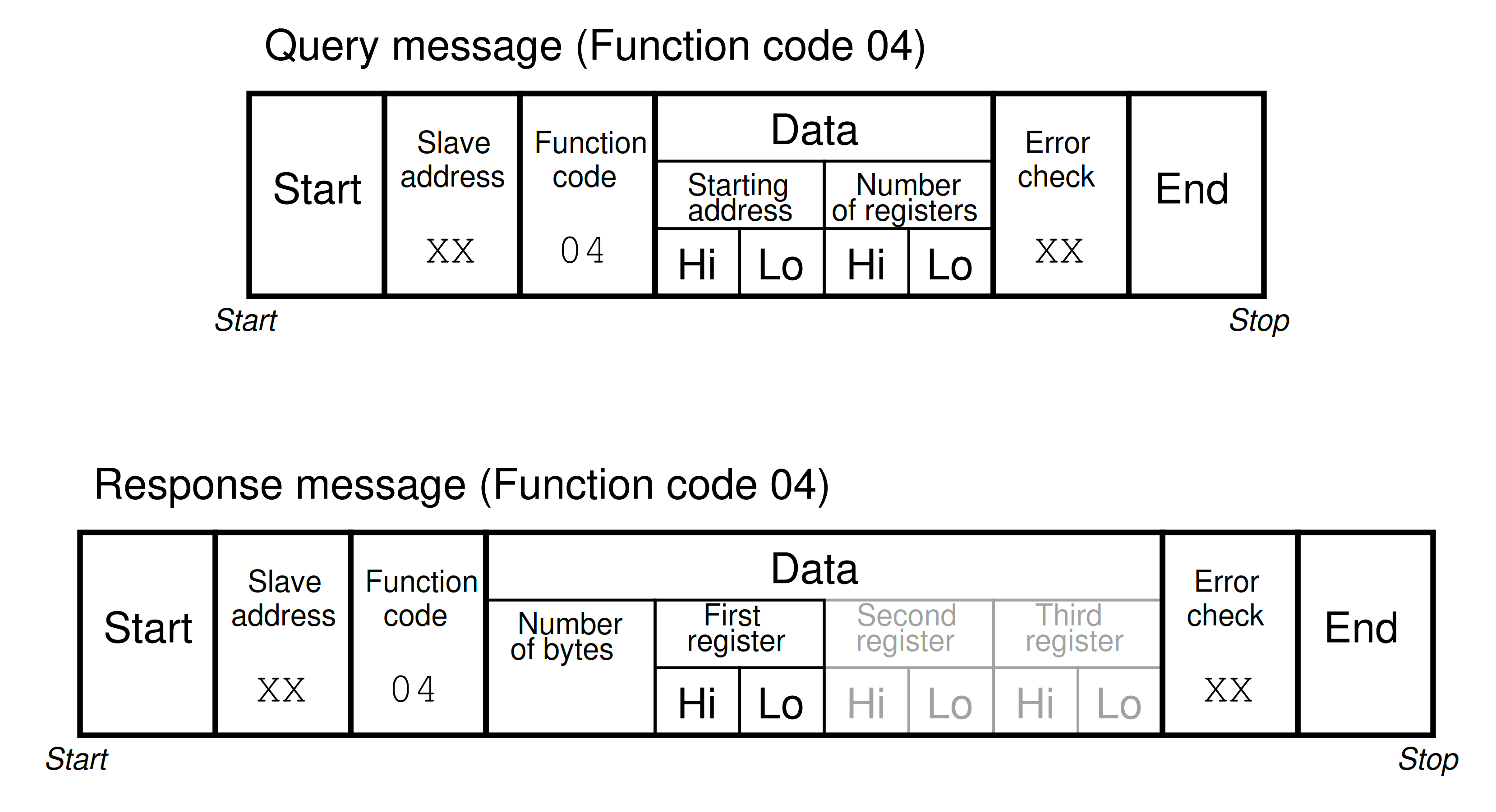
Note that since the query message specifies the number of registers (each register being two bytes in size), and the response message replies with the number of bytes, the response message’s “number of bytes” field will have a value twice that of the query message’s “number of registers” field.
Note also that the maximum number of registers which may be requested in the query message (65536) with “Hi” and “Lo” byte values grossly exceeds the number of bytes the response message can report (255) with its single byte value.
Modbus Function Code 05 – Write (Force) Single Coil
This Modbus function writes a single bit of data to a discrete output (“coil”) within the slave device.
Relevant Modbus addresses for this function range from 00001 to 09999 (decimal) but the starting address is a hexadecimal number representing the (n -1)th register from the beginning of this range (e.g. absolute decimal address 07200 would be specified as hexadecimal 0x1C1F, the “Hi” byte being 1C and the “Lo” byte being 1F).

The “force data” for a single coil consists of either 00 00 (force coil off) or FF 00 (force coil on). No other data values will suffice – anything other than 00 00 or FF 00 will be ignored by the slave device.
A normal response message will be a simple echo (verbatim repeat) of the query message.
Modbus Function Code 06 – Write (Preset) Single Holding Register
This Modbus function writes data to a single “holding” register within the slave device.
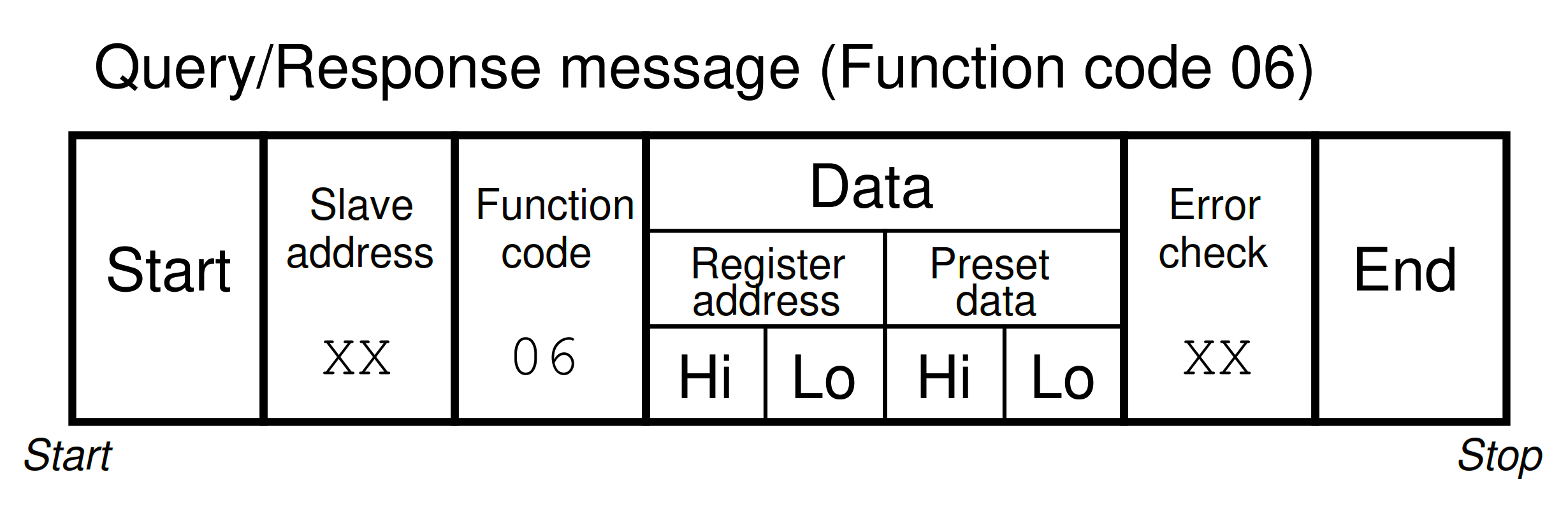
Relevant Modbus addresses for this function range from 40001 to 49999 (decimal) but the starting address is a hexadecimal number representing the (n -1)th register from the beginning of this range (e.g. absolute decimal address 40034 would be specified as hexadecimal 0x0021, “Hi” byte 00 followed by “Lo” byte 21).
A normal response message will be a simple echo (verbatim repeat) of the query message.
Modbus Function Code 15 – Write (Force) Multiple Coils
This Modbus function writes multiple bits of data to a set of discrete outputs (“coils”) within the slave device.
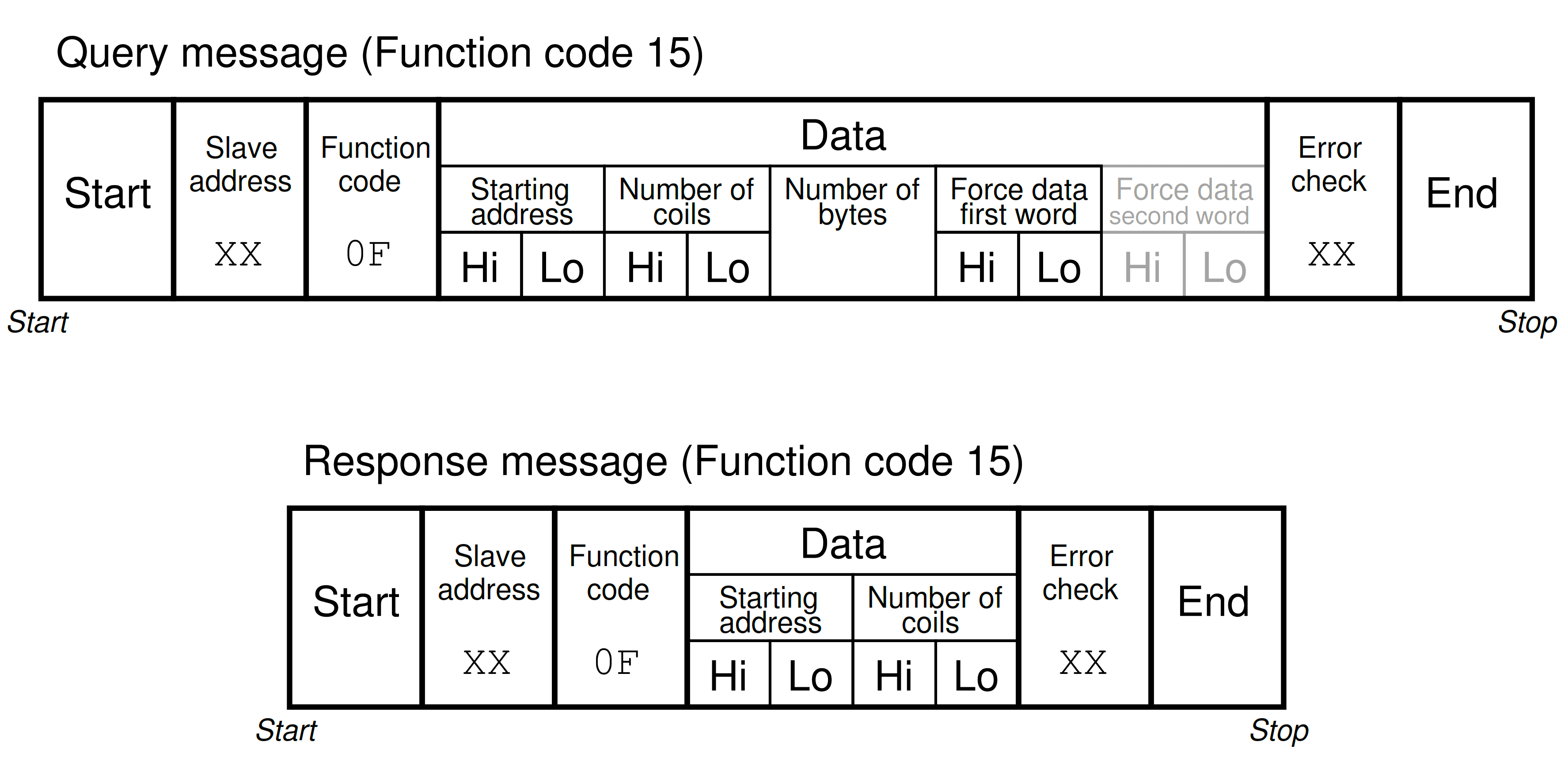
Relevant Modbus addresses for this function range from 00001 to 09999 (decimal) but the starting address is a hexadecimal number representing the (n -1)th register from the beginning of this range (e.g. absolute decimal address 03207 would be specified as hexadecimal 0x0C86, as a “Hi” byte 0C and a “Lo” byte 86).
Note that the query message specifies both the number of coils (bits) and the number of bytes.
Modbus Function Code 16 – Write (Preset) Multiple Holding Register
This Modbus function writes multiple words of data to a set of “holding” registers within the slave device.
Relevant Modbus addresses for this function range from 40001 to 49999 (decimal) but the starting address is a hexadecimal number representing the (n -1)th register from the beginning of this range (e.g. absolute decimal address 47441 would be specified as hexadecimal 0x1D10, a “Hi” byte of 1D followed by a “Lo” byte of 10).
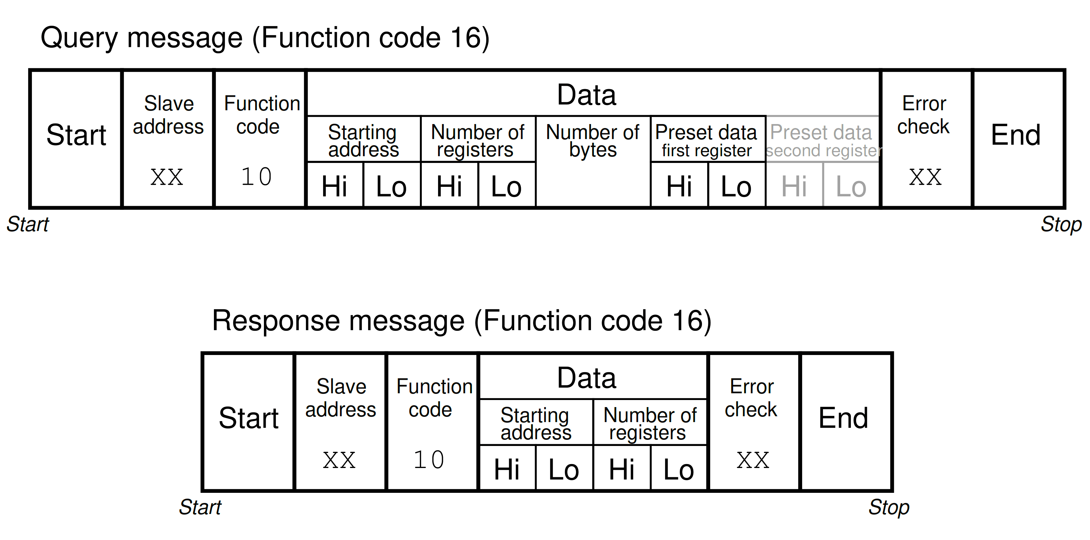
Note that the query message specifies both the number of registers (16-bit words) and the number of bytes, which is redundant (the number of bytes must always be twice the number of registers, given that each register is two bytes (Point 1) in size).
Note also that the maximum number of registers which may be requested in the query message (65536) with “Hi” and “Lo” byte values grossly exceeds the number of bytes the response message can report (255) with its single byte value.
Point 1: Even for devices where the register size is less than two bytes (e.g. Modicon M84 and 484 model controllers have 10 bits within each register), data is still addressed as two bytes’ worth per register, with the leading bits simply set to zero to act as placeholders.
© 2019-2021 by Tony R. Kuphaldt – under the terms and conditions of the Creative Commons Attribution 4.0 International Public License