In electrical signalling an analog current loop is used where a device must be monitored or controlled remotely over a pair of conductors. Only one current level can be present at any time.
A major application of current loops is the industry de-facto standard 4–20 mA current loop for process control applications, where they are extensively used to carry signals from process instrumentation to PID controllers, SCADA systems, and programmable logic controllers (PLCs).
They are also used to transmit controller outputs to the modulating field devices such as control valves. These loops have the advantages of simplicity and noise immunity, and have a large international user and equipment supplier base.
Some 4–20 mA field devices can be powered by the current loop itself, removing the need for separate power supplies, and the “smart” HART protocol uses the loop for communications between field devices and controllers. Various automation protocols may replace analog current loops, but 4–20 mA is still a principal industrial standard.
4–20 mA Process Control Loops
In industrial process control, analog 4–20 mA current loops are commonly used for electronic signalling, with the two values of 4 & 20 mA representing 0–100% of the range of measurement or control.
These loops are used both for carrying sensor information from field instrumentation, and carrying control signals to the process modulating devices, such as a valve.
Control Loops
The below figures Shows the evolution of analogue control loop signalling from the pneumatic era to the electronic era.


The key advantages of the current loop are:
- The loop can often power the remote device, with power supplied by the controller, thus removing need for power cabling. Many instrumentation manufacturers produce 4–20 mA sensors which are “loop powered”.
- The “live” or “elevated” zero of 4 mA allows powering of the device even with no process signal output from the field transmitter.
- The accuracy of the signal is not affected by voltage drop in the interconnecting wiring.
- It has high noise immunity as it is low impedance circuit usually through twisted pair conductors.
- It is self-monitoring; currents less than 3.8 mA or more than 20.5 mA are taken to indicate a fault.
- It can be carried over long cables up to the limit of the resistance for the voltage used.
- In line displays can be inserted and powered by the loop, as long as total allowable loop resistance is not exceeded.
- Easy conversion to voltage using a resistor.
- Loop powered “I to P” (current to pressure) converters can convert the 4–20 mA signal to a 3–15 psi pneumatic output for control valves, allowing easy integration of 4–20 mA signals into existing pneumatic plant.
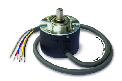
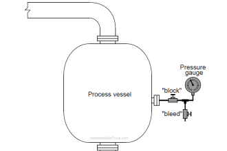
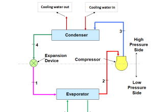
Field instrumentation measurements are such as pressure, temperature, level, flow, pH or other process variables. A current loop can also be used to control a valve positioner or other output actuator.
Since input terminals of instruments may have one side of the current loop input tied to the chassis ground (earth), analog isolators may be required when connecting several instruments in series.
The relationship between current value and process variable measurement is set by calibration, which assigns different ranges of engineering units to the span between 4 and 20 mA.
The mapping between engineering units and current can be inverted, so that 4 mA represents the maximum and 20 mA the minimum.
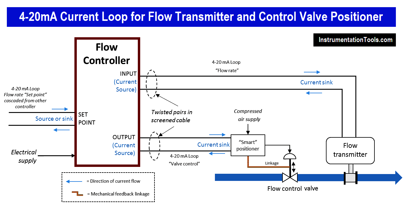
This example shows the versatility of the 4-20 mA current loop system in multiple applications. It can be used to cascade a set point from another controller, and it can both control and supply power to passive field devices which “sink” the current. In each loop there has to be one source of current, usually the controller.
Here a current loop is connected directly to a modern “smart” valve positioner. This is a local servo-controller that ensures the valve goes to the required position using a mechanical feedback linkage.
Active and Passive Devices
Depending on the source of current for the loop, devices may be classified as active (supplying or “sourcing” power) or passive (relying on or “sinking” loop power).
For example, a chart recorder may provide loop power to a pressure transmitter. The pressure transmitter modulates the current on the loop to send the signal to the strip chart recorder, but does not in itself supply power to the loop and so is passive.
Another loop may contain two passive chart recorders, a passive pressure transmitter, and a 24 V battery. (The battery is the active device). Note that a 4-wire instrument has a power supply input separate from the current loop.
Panel mount displays and chart recorders are commonly termed ‘indicator devices’ or ‘process monitors’. Several passive indicator devices may be connected in series, but a loop must have only one transmitter device and only one power source (active device).
History of Control Signals
The 4–20 mA convention was born in the 1950s out of the earlier highly successful 3–15 psi pneumatic control signal standard, when electronics became cheap and reliable enough to emulate the older standard electrically.
The 3–15 psi standard had the same features of being able to power some remote devices, and have a “live” zero. However the 4–20 mA standard was better suited to the electronic controllers then being developed.
The transition was gradual and has extended into the 21st century, due to the huge installed base of 3–15 psi devices. As the operation of pneumatic valves over motorised valves has many cost and reliability advantages, pneumatic actuation is still an industry standard.
To allow the construction of hybrid systems, where the 4–20 mA is generated by the controller, but allows the use of pneumatic valves, a range of current to pressure (I to P) converters are available from manufacturers. These are usually local to the control valve and convert 4–20 mA to 3–15 psi (or 0.2–1.0 bar).
This signal is then fed to the valve actuator or more commonly, a pneumatic positioner. The positioner is a dedicated controller which has a mechanical linkage to the actuator movement. This ensures that problems of friction are overcome and the valve control element moves to the desired position. It also allows the use of higher air pressures for valve actuation.
With the development of cheap industrial micro-processors, “smart” valve positioners have become available since the mid-1980s and are very popular for new installations. These include an I to P converter, plus valve position and condition monitoring. These latter are fed back over the current loop to the controller, using such as the HART protocol.
If you liked this article, then please subscribe to our YouTube Channel for PLC and SCADA video tutorials.
You can also follow us on Facebook and Twitter to receive daily updates.
Read Next:


Sir I am a huge fan of this site and follow it regularly. Everyday the site gives us new articles but everytime it is not possible for me to go through the article. So how can I check the previous articles?
Very good
This site is really helpful in my profession . Day by day I am gaining more and more knowledge on this subject.
Hello sir I am a Instrumentation and Control Engineer..Currently working in Automation Industry..which have 1 year n 4 month experience in that company as a PLC program(Control Department)..I have also works on site in Delhi , Rajasthan , Manesar…now i searching for another job in Pune..if in ur contact any company have openings or a vacancies plz suggest me..my gmail us laptop552@gmail.com