Industrial Process Plant Projects usually include Compressors as packages which are designed and supplied during Detail Design Engineering.
Such compressor packages may be driven by Motor or Turbine and due to size or project requirements may be considered medium or big packages, while they are considered Long Delivery Packages. The cycle time of Design, Engineering, Manufacturing / Assembly, Test and Delivery, Installation, Commissioning, Start-up, and Operation of such packages needs a lot of time. However, due to the different (I&C) technical points of such packages, they are categorized as Complex Packages.
Turbo-Compressor Package
In different projects and based on project requirements the driver side (Motor or Turbine) may be considered as a separate package that is supplied by its own vendor or it may be considered as part of the complex package (Driver + Driven) supplied by one vendor (Driver Vendor may be Sub-Vendor or Joint Vendor of main package vendor).
Usually, Compressor Packages with Turbine drives have more complexities than those with Motor drives, hence in the following of this article we will focus on the first one and use the word Turbo-Compressor as the package name.
Please notice that if the Driver (Motor or Turbine) is supplied by a separate vendor, then two separate packages shall be followed by the originators and the I&C Team, and so such specialists shall have serious care on coordination of interfacings/interactions between two packages, While if the whole package is supplied by one vendor, all internal interfacings between Driver and Driven sides of the package will be in vendor responsibilities.
Therefore considering Driver and Driven sides as parts of one complete package may have some advantages. One of the main advantages of such complete package consideration is referred to consider common (process) blocks for two packages instead of considering two dedicated items (lube oil as an example).
Another advantage is the best guaranteed mechanical integrity and matching of both packages. Similarity and uniformity of instrumentations (types, models, brands, wirings,…) between two packages is another advantage.
Turbo-Compressor System Architecture Diagram
Using a Systems Architecture Diagram will help us to better define and represent the project requirements to Turbo-Compressor vendor similar to other project packages (see the article mentioned in the Reference section for advantages of providing such a document at Detail Engineering Company).
Figure 1 shows one schematic diagram attached to the Turbo-Compressor Material Requisition for defining the project requirements. This diagram was provided in Detail Engineering Company and can be used as a typical schematic (for several similar packages or requisitions) or may be added in more detail and separately to each specified Turbo-Compressor package requisition of the project.
Figure-1: Schematic Diagram for Turbo-Compressor Control System (may be used as Typical Packages or may be used for definition on exact specified Package
If the I&C Team of the project provides such a diagram in the same approach of Process Plant System Architecture with a similar format it may be more useful (see referenced article). By such consideration, Figure 2 may be a better representation of project requirements (which is provided based on the Process Plant System Architecture Diagram).
Figures 1 and 2 as schematic diagrams show project requirements just as general blocks and connections, while by following some rules and legend symbols, the reader can easily find the overview of all Turbo-Compressor package needs. Let us review Figure 2 for such considerations.
Project Locations Relevant To Package
By this diagram, the vendor knows that the package skid(s) will be installed at the project Field (/Site) while the control cabinets/ panels are located in the Cabinet (/Auxiliary) Room.
However, the package will be equipped with some Local Panels and a Local Gauge Board at the Field too. If the Turbo-Compressor was in the Compressor House Building, the additional block should be added around the package skid to define exactly such location.
However, by the currently shown diagram, there is no Compressor House was considered. So the package vendor understands that their package is requested to be ‘Outdoor’ type (and all required protections shall be considered by them).
Otherwise, if they need extra protection or some special environmental conditions, they shall ask the customer for such a discussion. The most important characteristics related to the ‘Outdoor’ facility of the package in process plants are Hazardous Area Classifications and Ingress Protection.
So the vendor shall have exact care regarding the selection of equipment and instruments to have suitable explosion-proof and IP protection (which of course will have effects on their commercial estimations).
Figure 2: Turbo-Compressor Package Control Interfacing (Typical Diagram provided in Detail Engineering Company for definition /clarification of project package requirements).
Package Skids and Equipment Scope of Supply
Referring to Figure 2 we may find that all mechanical items of the package (including all equipment and installed instruments) are in the vendor’s scope of supply. Of course, details of all required mechanical parts are specified in other Material Requisition attached documents including P&IDs and Equipment Datasheets.
In fact from a Turbo-Compressor System Architecture point of view, the number and detail of package (mechanical) skids and equipment are not the main concern, but instead considering all required instruments and connection facilities for different items (Junction Boxes = JB’s) shall be exactly considered by vendor.
However, required specifications for I&C items are explained in other documents which shall be considered by the vendor too. One important point that shall be considered carefully by the I&C Team and vendor specialists during clarifications (and negotiation) is related to instruments that are located on skids interfaces with each other or with process plants.
Such items if supplied by the vendor, usually are supplied as loose items that shall be installed at the project site (with exact precautionary discussion on installation and connection procedures).
Wiring Connections and Cabling for Package
Since the package vendor doesn’t know the exact routes between different locations of the project site, and also considered design facilities on cable routines.
It is clear that the connection cables between different locations are out of the scope of package supply (this subject is shown on the diagram by exact definition), while special cables or connection cables on skids (from instruments to junction boxes or local panels) are (usually) in vendor’s scope of supply.
I&C cables and Electrical cables (Motors, LCS, and MCC interface) shall be discussed with the vendor in this way. Cables inside the buildings and connection facility at battery limits (like cable entry size, cable gland, and motor terminal boxes) shall be negotiated and clarified exactly between the vendor and I&C Team too.
Local Panels and Local Control Stations for Package
Refer to Figure 2, The Vendor and I&C Team shall discuss and clarify the required local panels (and gauge boards) and local control stations for the motors’ local start/stop facility.
Of course, details of such items shall be clarified in vendor detail design documents. Similar to Junction Boxes, the wiring and cable connection of these items shall be discussed and clarified too.
Turbo-Compressor Package Cabinets
Refer to Fogure-2 a set of cabinets (or panels) shall be considered for implementing required systems and functions, which are installed in the Cabinet (Auxiliary) Room of the Control Building.
This diagram shows schematically for scope of supply of such cabinets and required functions, while in vendor detail design documents the exact data and information shall be mentioned.
However vendor may be requested to estimate some important data at an early stage of the project (Bid Stage) like the quantity and arrangement of such cabinets or electrical power consumption. Such data are required for designing the control room layout and estimating the required UPS Power size, by the I&C Team.
PLC for Turbo-Compressor Package
The turbo-compressor package is a complex package that needs control and safety function processors (systems). For implementing such functions Turbo-Compressor package often includes one or two PLCs.
Since the Turbo-Compressor package is usually a critical package in the process plant, so control performance and safety functions of it are considered seriously important, which leads to have predefined level of SIL for such PLCs (as an example SIL-3 in Figure-2).
Due to commercial points, the package vendor may offer one PLC for both control and Safety functions, but he shall guarantee the required achievable SIL level on package SIFs. However PLC (or PLC’s) shall have an HMI Operator Panel further to the Programming /Engineering Station (maybe as a laptop).
Turbo-Compressor Signal Interfaces with Plant DCS & ESD
Turbo-Compressor Package as an important package of process plants shall have some signal interfaces with plant control and safety systems (DCS and ESD).
Details of minimum required signals are shown on P&IDs and may be described in the Material Requisition attached documents.
In Turbo-Compressor System Architecture Diagram just schematic hardware connections of such signal interfaces are shown. Also, Serial Link Communication is considered for transferring almost all package signals too.
Turbo-Compressor Signal Interfaces with Plant MCC
Package Motors Control Philosophy shall be discussed and clarified with the Electrical Team and required interfacing signals shall be defined accordingly.
Turbo-Compressor System Architecture just shows these interfacing signals schematically.
Turbine Governor System
For controlling the speed of the turbine, the package needs one Turbine Governor System, which may be supplied as a dedicated block (installed in package cabinets) or may be processed by Package PLC with a special application program (depending on the vendor’s offers).
Turbine Over-Speed Protection System
Usually, this protection function is supplied by a dedicated system which is installed in package cabinets.
Turbo-Compressor Machine Monitoring System
Nowadays every rotary machine like a turbine or compressor is monitored and protected with a Machine Monitoring System and accordingly Condition Monitoring System. Such a system may be requested for each turbo-compressor package dedicatedly or the customer may prefer to consider one system to support several packages including pumps or Turbo-Compressors.
Such a system shall be discussed clearly with the vendor for the supplier of it. In any case, usually, the required protection probes shall be installed by the Turbo-Compressor vendor, and so they shall provide such instruments based on the agreed-selected Machine Monitoring System.
Turbine-pumps or Turbo-pumps packages are some similar packages to Turbo-Compressor packages, in which the driven part is pump instead of the compressor.
Figure 3 shows a Control System Block Diagram for a complex Turbo-Pumps package which has some separated Machine Monitoring Systems (racks) for each pump with one common Condition Monitoring System for all pumps.
Figure 3: Boiler Feed Water Pumps Package Control Block (Interfacing) Diagram
Turbo-Compressor Special Facility Systems
In some packages due to the type of process or due to customer requests some extra systems shall be supplied by the Turbo-Compressor package too.
Anti-Surge Controller and Annunciator (panel) may be considered as examples of such items.
Turbo-Compressor Vendor System Architecture
Turbo-Compressor vendor shall represent their own System Architecture in a general block diagram at the bid stage of the project, and they shall provide details of the System Architecture during detail design by them.
However, if they follow the prepared design document for the Turbo-Compressor package ( by the I&C Team of Detail Design Engineering Company), the mutual understanding between vendor and customer will be followed easily and faster. Figure 4 is a realistic sample of the Turbo-Compressor Vendor System Architecture provided based on the design document system architecture.
Figure-4: Vendor “Turbo-Compressor Package Control Interfacing Diagram” document (This document may be issued as Turbo-Compressor Vendor System Architecture).
Figure 5 shows another realistic sample of Turbo-Compressor Vendor System Architecture which is provided just based on project requirement descriptions (without any design document Turbo-Compressor System Architecture).
Although the vendor provided a good system architecture, but for studying such a diagram, the following points shall be considered:
- The vendor was very well qualified and based on explanations and comments they could reach to satisfy project requirements well. If the vendor is weak qualified you cannot expect such a good diagram.
- The early issue of such a diagram was primarily during the time and after several comments and clarifications, such a document was finalized. In some projects, the finalization process of documents may take a long time.
- Although the document has many details on the final issue in comparison to the design document (especially at the early stage) there is little conformity in the structure format with it. So in the whole project, we may have not a uniform structural format of documents (on different project packages) for better and faster understanding.
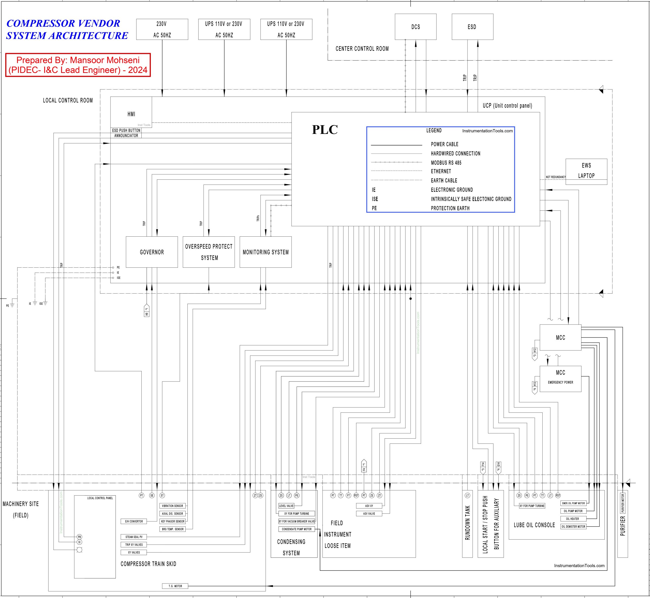
Figure-5: Vendor “Turbo-Compressor Package Control Interfacing Diagram” document (This document may be issued as Turbo-Compressor Vendor System Architecture).
Use of Design Document for Package Systems Architecture
As we can conclude by studying the design document of Turbo-Compressor System Architecture Diagram, such document may explain some project requirements directly, while for some items it works like a checklist to remind vendor and customer to discuss and negotiate for clarification of them. However, it can be easily revised based on project and vendor agreements.
As an example consider that in some projects vendor and customer may have an agreement to implement the required control and safety functions of the package, inside the plant control and safety systems (DCS and ESD).
In such cases, the package cabinets may include some limited systems with less panel quantity. Such a case may have some advantages, while it is very hard and needs at least very close coordination of vendor and customer for transferring exact Logic/ Interface Diagram further to Control Loops requirements. However, such a case can be shown on the design document Turbo-Compressor System Architecture Diagram with some easy document modifications.
Referring to Figure 3 may help us understand the above-mentioned explanations but for the complex package of Turbo-Pumps.
References:
- Package Systems Architecture
- Instrumentation Project Packages
- Design Documents for Project Architecture
- Vendor Documents for Project Architecture


Very good exhibition. Many Thanks