We are going to use a P-AOUT Analog output Add-on block for the configuration of a Control Valve in studio 5000 and, we will see Analog Output parameters descriptions which we are going to configure.
Configuration of Control Valve in Studio 5000
Follow the below steps for the configuration of the control valve in Studio 5000.
Step 1:
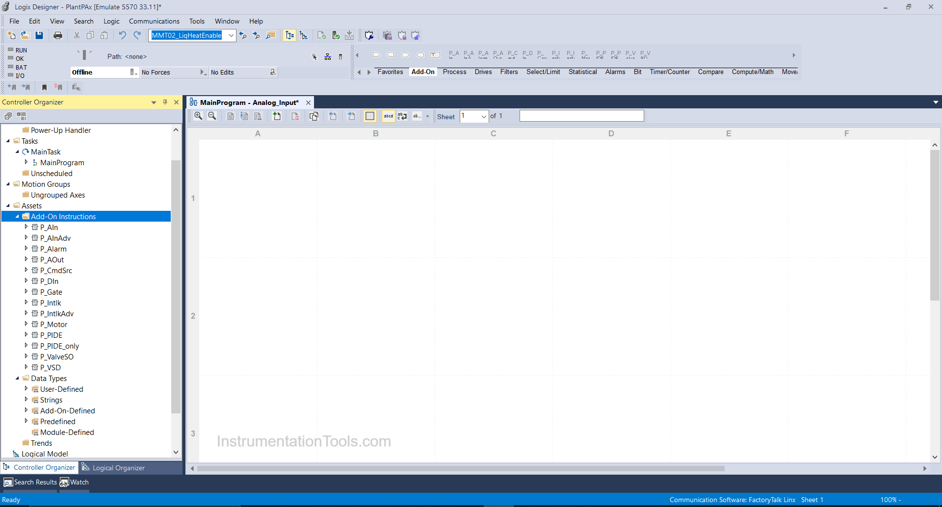
Open Logix designer and open PlantPAx Project file in which all required add-on blocks of PlantPAx library are imported.
Step 2:
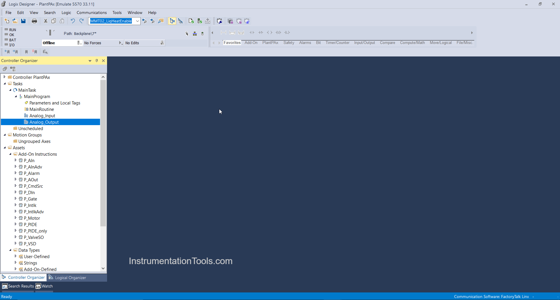
Right Click on Main Program and create a new routine as Analog Output.
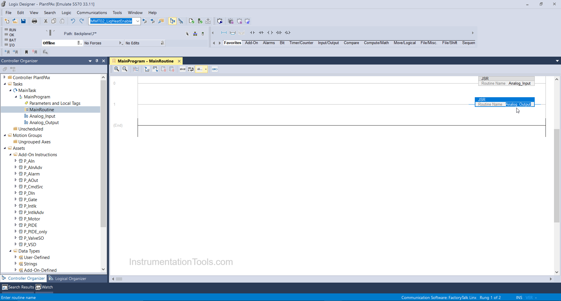
And in the main program, calls the routine using JSR Instruction as shown below.
Step 3:
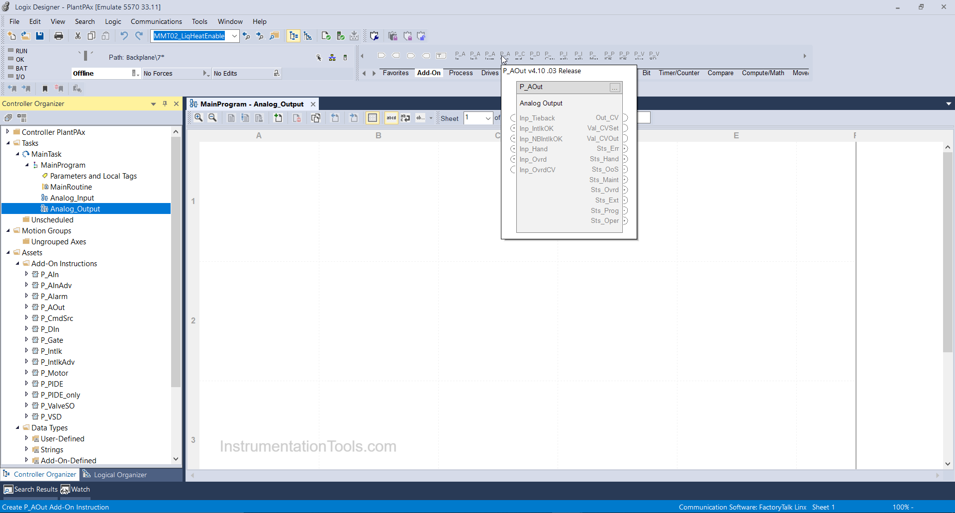
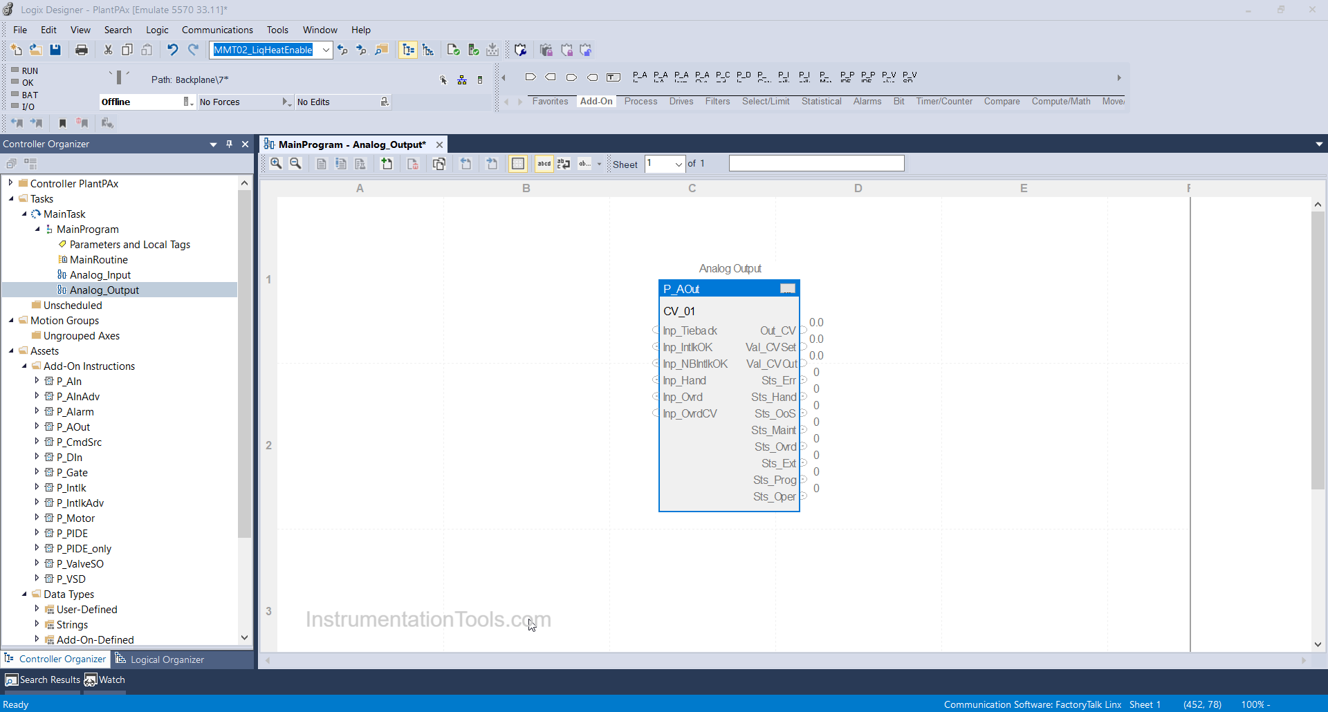
Double click on the Analog Output routine and click on add-on and select P-AOUT instruction as shown below.
Step 4:
After adding the P_AOUT block we will bind a tag as CV_01 (Control valve 01) in the controller scope.
Step 5:
After that, click on the 3 dots tab and the parameter window will open where you can select and force the parameters you want.
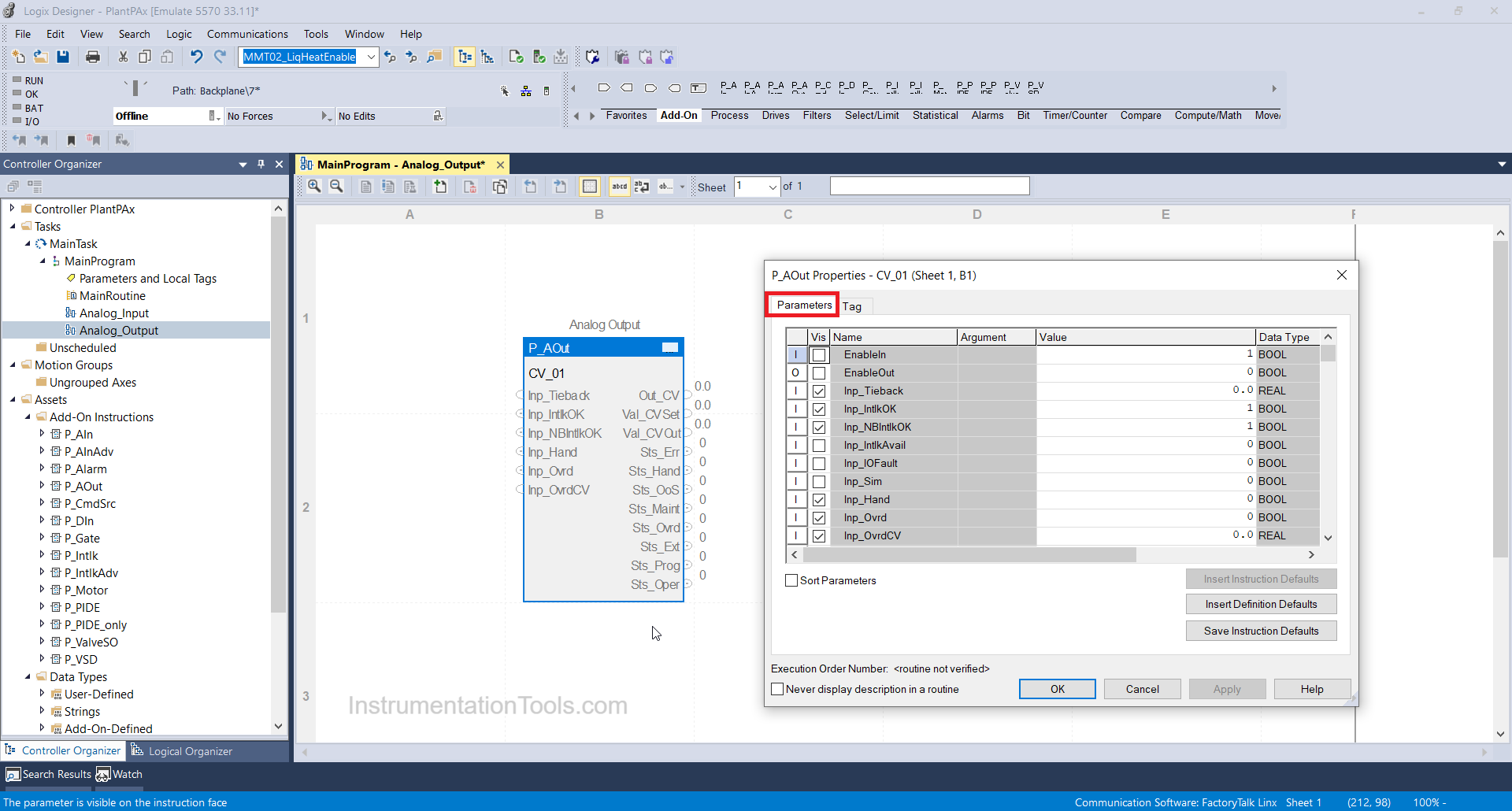
Inp-tieback: It indicates tieback CV i.e raw output of CV units.
Inp-IntlkOK: If it indicates=1 then all interlocks configured for particular valves are OK.
Inp-NBIntlkOK: It indicates those interlocks which cannot be bypassed are OK or not.
Inp-Ovrd: It indicates whether the input is overridden or not i.e if value=1 then particular input I override and if it is=0 then it is healthy.
Inp-OvrdCV: Target CV can be overridden.
Out CV: It indicates the simulated raw output value of the Control valve.
Sts-Err: It indicates that the control valve is in error. It means input failure.
Sts-Maint: It indicates the control valve is in maintenance mode.
Sts-Prog: It denotes Valve is in program mode.
Sts-Oper: It indicates Valve is in Operator mode.
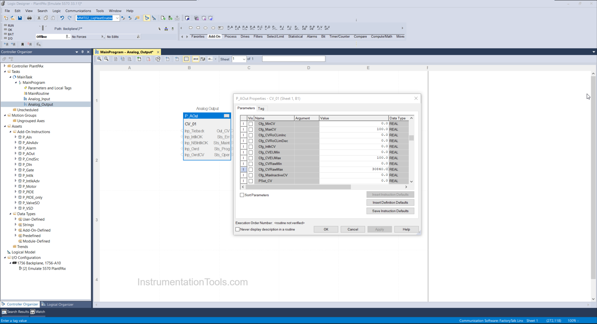
Step 6:
Now we are going to enter the raw count and its engineering value accordingly which the actual valve will modulate. Enter 0 to 30840 in Raw min and Raw max as shown below and 0 to 100 will be your actual valve target value in%.
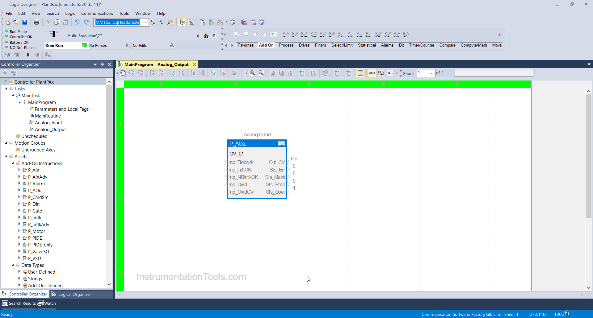
Step 7:
Your valve is configured you can test as shown below, download the logic/routine file in your available controller or in the emulator as I have done.
If you liked this article, then please subscribe to our YouTube Channel for Instrumentation, Electrical, PLC, and SCADA video tutorials.
You can also follow us on Facebook and Twitter to receive daily updates.
Read Next:
- PlantPAx Control System
- Import PlantPAx Library
- DCS Technical Evaluation
- Download PlantPAx Library
- Compressor Start Permissive


how to show failed to open and failed to close in Control valve
Am from tanzania , I need plc software to install in my computer