Inst ToolsInst ToolsInst Tools
  • Courses
  • Videos
  • Q & A
    • Interview
      • Instrumentation
      • Electronics
      • Electrical
      • Practical Questions
    • MCQ
      • Instrumentation MCQ
      • Electrical MCQ
      • Electronics MCQ
      • Control Systems MCQ
      • Analog Electronics MCQ
      • Digital Electronics MCQ
      • Power Electronics MCQ
      • Microprocessor MCQ
      • Multiple Choice Questions
  • EE
    • Electronics
      • Electronics Q & A
      • Electronic Basics
      • Electronic Devices & Circuits
      • Electronics Animation
      • Digital Electronics
    • Electrical
      • Electrical Basics
      • Electrical Q & A
      • Power Electronics
      • Electrical Machines
      • Electrical Animation
      • Power Systems
      • Switchgear & Protection
      • Transmission & Distribution
  • Measure
    • Control Valves
    • Calibration
    • Temperature
    • Pressure
    • Flow
    • Level
    • Analyzers
    • Switches
    • Vibration
    • Solenoid Valve
  • Control
    • PLC Tutorials
    • Control Systems
    • Safety Instrumented System (SIS)
    • Communication
    • Fire & Gas System
  • More
    • Design
    • Tools
    • Animation
    • Basics
    • Formulas
    • Standards
    • TextBooks
    • Common
    • Software
    • Excel Tools
    • Erection & Commissioning
    • Process Fundamentals
    • Videos
    • Books
Search
All rights reserved. Reproduction in whole or in part without written permission is prohibited.
Reading: Types of Surge Control for Parallel Gas Compressors
Share
Notification Show More
Font ResizerAa
Inst ToolsInst Tools
Font ResizerAa
  • Courses
  • PLC Tutorials
  • Control Systems
Search
  • Courses
  • Videos
  • Q & A
    • Interview
    • MCQ
  • EE
    • Electronics
    • Electrical
  • Measure
    • Control Valves
    • Calibration
    • Temperature
    • Pressure
    • Flow
    • Level
    • Analyzers
    • Switches
    • Vibration
    • Solenoid Valve
  • Control
    • PLC Tutorials
    • Control Systems
    • Safety Instrumented System (SIS)
    • Communication
    • Fire & Gas System
  • More
    • Design
    • Tools
    • Animation
    • Basics
    • Formulas
    • Standards
    • TextBooks
    • Common
    • Software
    • Excel Tools
    • Erection & Commissioning
    • Process Fundamentals
    • Videos
    • Books
Follow US
All rights reserved. Reproduction in whole or in part without written permission is prohibited.
Inst Tools > Blog > Control Systems > Types of Surge Control for Parallel Gas Compressors

Types of Surge Control for Parallel Gas Compressors

Last updated: November 3, 2019 6:18 pm
Editorial Staff
Control Systems
1 Comment
Share
4 Min Read
SHARE

Different Types of Surge Control for Parallel Gas Compressors are as follows.

Contents
Types of Surge ControlBase Load MethodSuction Side – Speed Control MethodEqual Flow Balance MethodEquidistant to Surge Line Method

Types of Surge Control

  1. Base Load Method
  2. Suction Side – Speed Control Method
  3. Equal Flow Balance Method
  4. Equidistant to Surge Line Method

Base Load Method

Compressor A Speed is manually set (HIC) for maximum flow & termed as ‘Base Load’ while Compressor B Speed via speed controller (SC) is swung based on Master Pressure Controller’s (PIC) Set Point (SP) to attend to remaining swing in flow variations (loads).
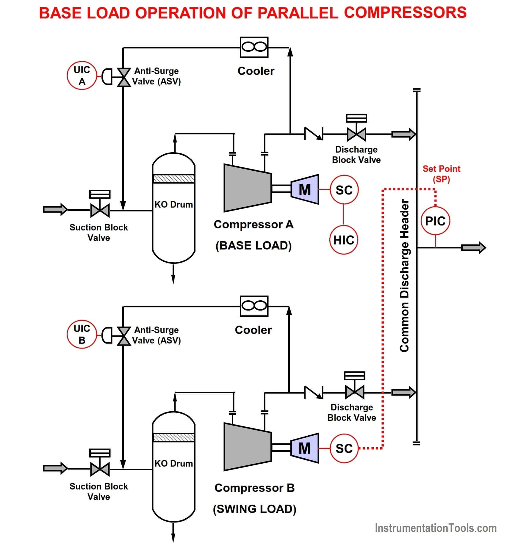
Base Load Operation of Parallel Compressors

During periods of low process demand, Compressor B (Swing Machine) can be recycling & sometimes even close enough to the Surge Control Line (SCL) causing the Swing Machine to Trip. Hence an inefficient configuration.

Base Load Operating Style requires frequent operator intervention.

A configuration that is not in vogue anymore & not recommended.

Suction Side – Speed Control Method

No Base Load Exists, but instead the Master Pressure Controller (PIC) is shifted to the suction side.

Master Pressure Controller (PIC) provides set point (SP) to speed controller (SC).
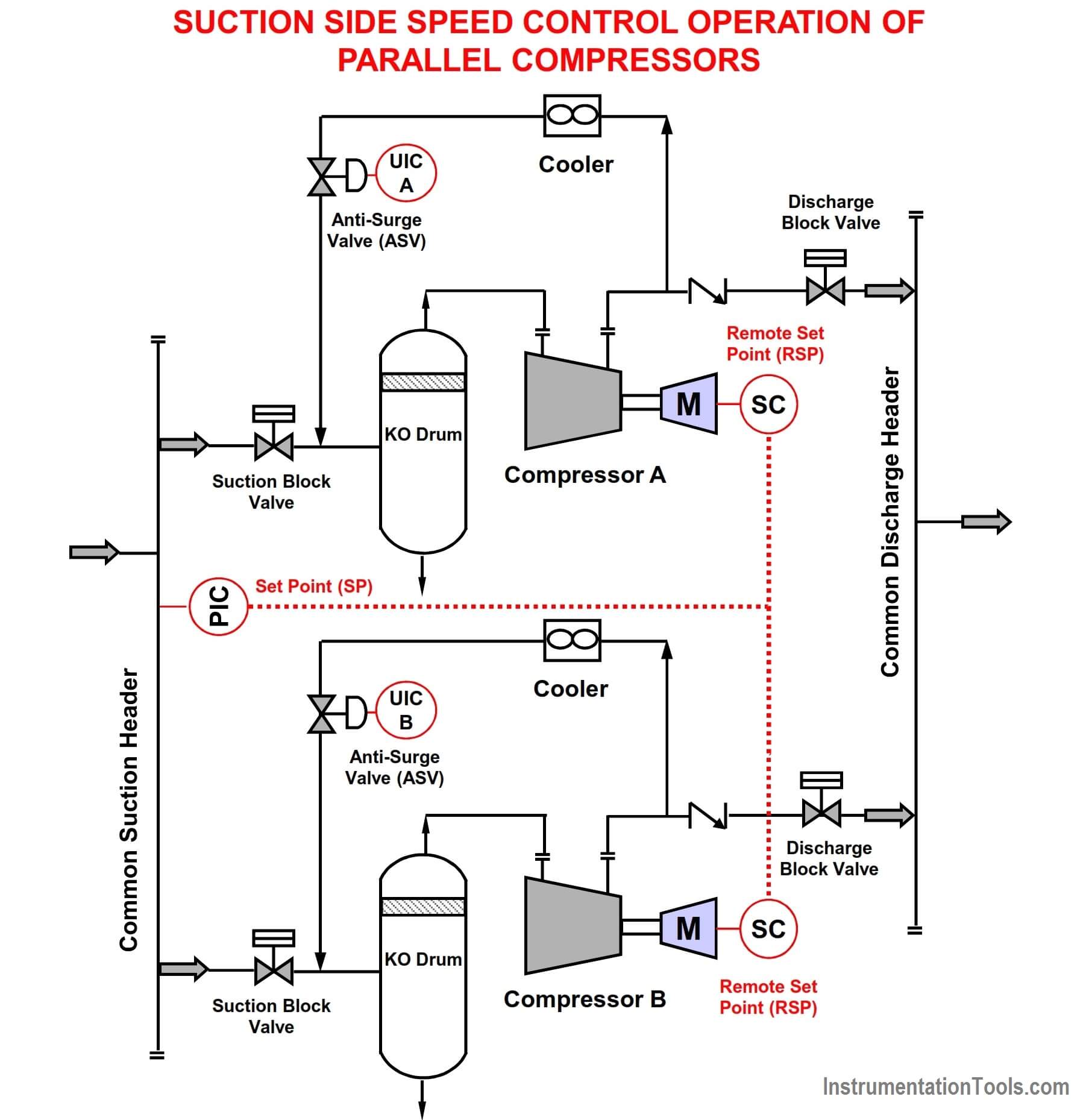
Suction Side Speed Control Operation of Parallel Compressors

Both Compressors would not necessarily operate at the same speed/flow during a recycle since UIC A/B are acting independently of each other.

Equal Flow Balance Method

The Master Pressure Controller (PIC) on the common discharge header determines the total load demand and alters Compressors A & B speeds (SC). The individual flow control signal to each speed controller is achieved by scaling the total load demand (Bias A & Bias B) to the individual flow controller (FC) on each compressor.

Both Compressor Operations are independent of the Anti-surge Valve (ASV) Operation.
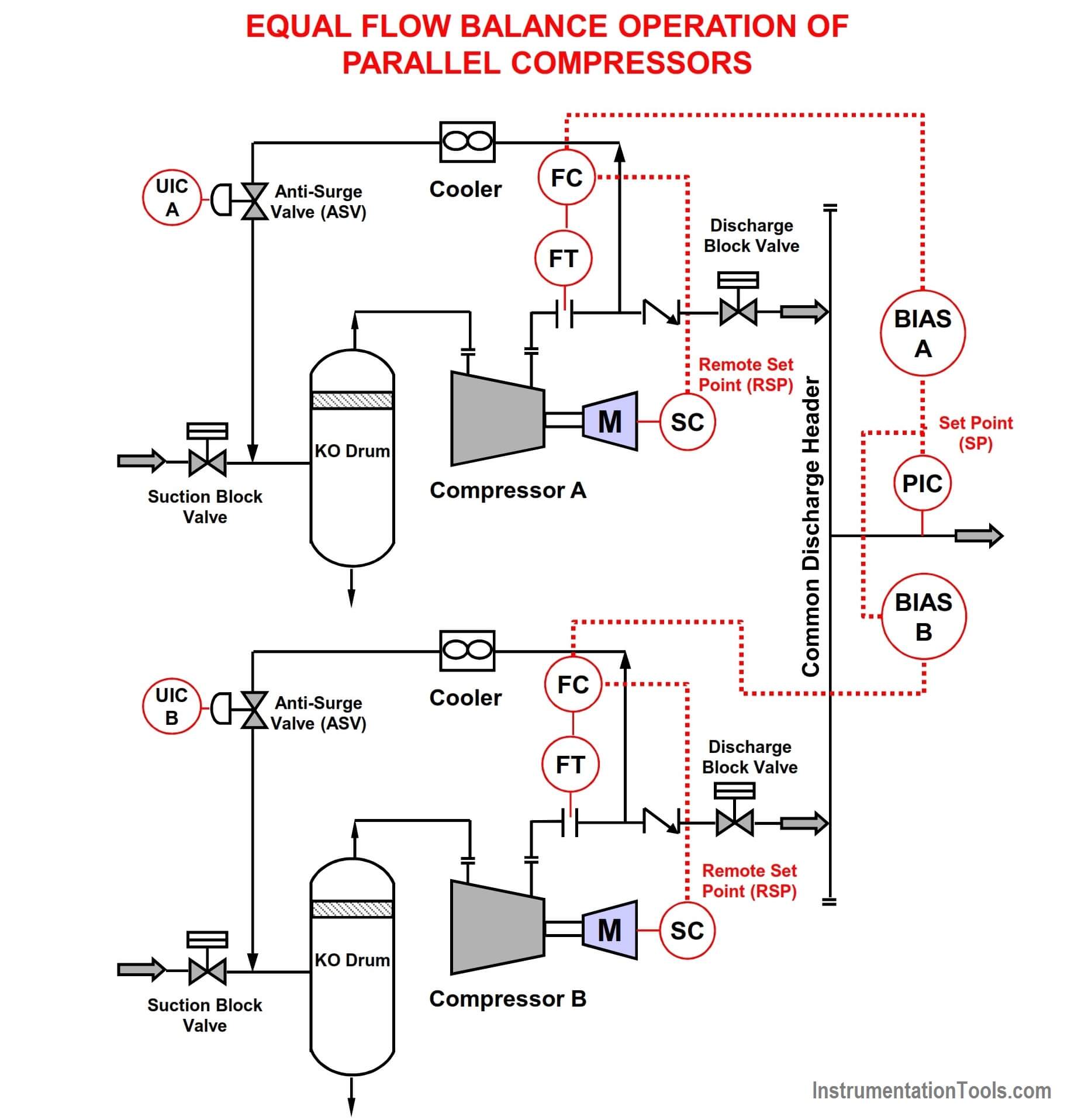
Equal Flow Balance Operation of Parallel Compressors

Flow Balancing method requires additional control elements thereby increasing CAPEX costs.

Since Flow Element & Transmitter (FT) is installed on the compressor discharge, additional pressure drop occurs representing energy losses & corresponding costs.

For the cascaded control used, PIC ➤ FC ➤ SC, the inner loop (FC) must respond faster than the PIC outer loop causing PIC to be sluggish. The faster FC loop also means, the compressor speed would increase faster than required often reaching maximum speed & hence does not offer the best control strategy.

Equidistant to Surge Line Method

Based on the principle –

The Deviation/Distance between the operating points & the surge control (SCL) line in both trains is equidistant.

For this configuration N1 ≠ N2 & Q1 ≠ Q2 , but Dev1 = Dev2 (i.e., Dev = Distance between Op. Point & Surge Line).
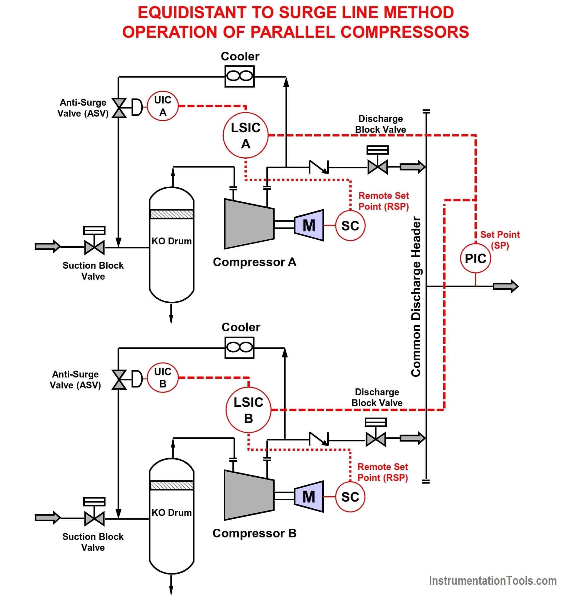
Equidistant to Surge Line Method Operation of Parallel Compressors

Both UIC A/B (Anti-surge Controller) & LSIC A/B (Load sharing Controller) would coordinate their responses in Real time.

Applicable also for parallel compressors that have dissimilar / asymmetrical performance curves.

An effective configuration for varying loads, that ensures both compressors independently adjust operations to stay away from surge.

About the Author :

Vijay Sarathy holds a Master’s Degree in Chemical Engineering from Birla Institute of Technology & Science (BITS), Pilani, India and is a Chartered Engineer from the Institution of Chemical Engineers, UK. His expertise over 10 years of professional experience covers Front End Engineering, Process Dynamic Simulation and Subsea/Onshore pipeline flow assurance in the Oil and Gas industry. Vijay has worked as an Upstream Process Engineer with major conglomerates of General Electric, ENI Saipem and Shell.

Articles You May Like :

Anti Surge Controller Principle
Instrument Air System Design

What is an Orifice Flange ?

Redundancy in Control System

Basics of PLC & BPCS System

Don't Miss Our Updates
Be the first to get exclusive content straight to your email.
We promise not to spam you. You can unsubscribe at any time.
Invalid email address
You've successfully subscribed !

Continue Reading

Three Element Drum Level Control System
PID Controller Parameters Tuning Manually
Difference Between Batch Process and Continuous Process
Switches, Repeaters, Bridges, Routers, Firewalls
VFD Simulator Download – Free Yaskawa V1000 Software
Override Control Functions
Share This Article
Facebook Whatsapp Whatsapp LinkedIn Copy Link
Share
1 Comment
  • Vamsi Krishna says:
    August 19, 2019 at 4:30 pm

    Thank you for the awesome explanation.

    Reply

Leave a Reply Cancel reply

Your email address will not be published. Required fields are marked *

Stay Connected

128.3kFollowersLike
69.1kFollowersFollow
208kSubscribersSubscribe
38kFollowersFollow

Categories

Explore More

Tips for Reducing the Noise Signals
Difference between Process shutdown and Emergency Shutdown
PID Controllers : Parallel, Ideal & Series
Voice Activated Industrial Automation Systems
Difference between Fieldbus, Profibus and HART Protocols
Process Interlocks and Trips
What is a Active Barrier ?
All About Fieldbus Protocols

Keep Learning

Electrical Drives Animation

Electrical Drives – Modes, Types, Speed Control Applications

Pressure and Level Control Loop

Problem on Pressure and Level Control Loops

Electrical Circuit Label Schematic

Label the Electrical Circuit Schematic

DCS ESD Logic Overview Graphic Display

Automation System Process Functionalities

Four Wire Current Loop

4-wire Transmitters Current Loops

Shielded Cables

The Idea Behind Shielded Cables

Process Control Instrumentation Terms Glossary

Process Control Instrumentation Glossary

Switches, Repeaters, Bridges, Routers, Firewalls

Purpose of Gateways, Bridges & Routers in Networking

Learn More

Thermocouple Law of Intermediate Metals

Thermocouples Law of Intermediate Metals

CNC Programming - Definition, Types, and Tips

CNC Programming – Definition, Types, and Tips

Simatic S7 PLC Backup Steps

How to take Backup from Siemens S7-300 PLC?

0-10 VDC to 0-20 mA Conversion

How to Convert Voltage to Current using Resistor ?

Siemens PLC Organization Blocks used For Troubleshooting

Tia Portal – OB121 Programming Errors Interrupt Organization Block

Conveyor Control with Main Motor and Backup Motor

Conveyor Operation with a Backup Motor using PLC Ladder Diagram

Is it Possible to Measure liquid-liquid Level Interface using Float

Is it Possible to Measure Liquid-Liquid Level Interface using Float?

Level Gauge Interface Measurement

Level Gauge Interface & Temperature Problems

Follow US
All rights reserved. Reproduction in whole or in part without written permission is prohibited.
Welcome Back!

Sign in to your account

Username or Email Address
Password

Lost your password?