Maintenance Override Switch (MOS) shall be provided to override all field inputs designated to trip the facility in order to facilitate maintenance of field devices without interrupting the plant operation.
Maintenance Override Switch
")
Following are some general condition applicable to MOS system:
There shall be a common MOS permissive key in the ESD operator panel have two positions i.e. ‘MOS-enabled’ and ‘MOS-off’. When key switch is in the MOS enabled position, there shall be a red status alarm on the ESD operator fascia panel, which shall flash until the MOS is off.
The alarm status of the field inputs, which are overridden by “MOS”, shall not be masked.
MOS switches for multiple field inputs used in voting systems shall be grouped together.
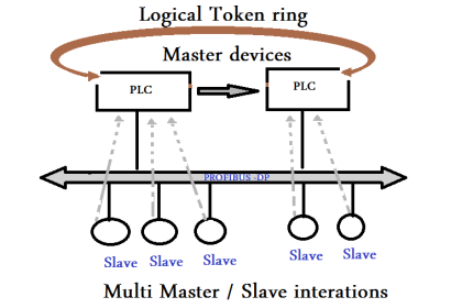
MOS for PLC based system
a) The MOS shall be software switches provided with password protection in the ESD/SSLS logic, unless otherwise specified.
b) MOS interfaces shall be configured tag-wise on the graphics of the ESD workstation.
c) Activation and release of MOS shall be logged into the alarm journals of the ESD / SSLS workstation and displayed graphically.
d) MOS for ESD system and SSLS shall be segregated and each separately grouped in the graphics.
e) The field inputs which need to be overridden by MOS to facilitate maintenance work, shall be alarmed as follows:
The tag number shall be in black foreground shrouded in a magenta box as long as the MOS is active, at DCS console graphic.
Also Read : Process Override Switch
The fill colour of MOS switch shall be “Red” if MOS is activated and; “Green” if MOS is normalised at the ESD workstation graphics.
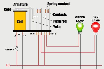
MOS for Relay based system
a) MOS shall be hardwired key locked switches mounted in the ESD cabinet, the interface cabinet or in an adjacent identical cabinet.
b) MOS activation shall input to the DCS and bring up an “override in operation” alarm and shall print on the event log.
c) The field inputs which need to be overridden by MOS to facilitate maintenance work, shall be alarmed at the DCS as detailed below:
The tag number shall be in black foreground shrouded in a magenta box as long as the MOS is active at DCS console graphic.
Author : Iqbal Matondang


So useful, Thank you,