Inst ToolsInst ToolsInst Tools
  • Courses
  • Automation
    • PLC
    • Control System
    • Safety System
    • Communication
    • Fire & Gas System
  • Instrumentation
    • Design
    • Pressure
    • Temperature
    • Flow
    • Level
    • Vibration
    • Analyzer
    • Control Valve
    • Switch
    • Calibration
    • Erection & Commissioning
  • Interview
    • Instrumentation
    • Electrical
    • Electronics
    • Practical
  • Q&A
    • Instrumentation
    • Control System
    • Electrical
    • Electronics
    • Analog Electronics
    • Digital Electronics
    • Power Electronics
    • Microprocessor
  • Request
Search
  • Books
  • Software
  • Projects
  • Process
  • Tools
  • Basics
  • Formula
  • Power Plant
  • Root Cause Analysis
  • Electrical Basics
  • Animation
  • Standards
  • 4-20 mA Course
  • Siemens PLC Course
Reading: Why Offset in Proportional Controller ?
Share
Notification Show More
Font ResizerAa
Inst ToolsInst Tools
Font ResizerAa
  • Courses
  • Design
  • PLC
  • Interview
  • Control System
Search
  • Courses
  • Automation
    • PLC
    • Control System
    • Safety System
    • Communication
    • Fire & Gas System
  • Instrumentation
    • Design
    • Pressure
    • Temperature
    • Flow
    • Level
    • Vibration
    • Analyzer
    • Control Valve
    • Switch
    • Calibration
    • Erection & Commissioning
  • Interview
    • Instrumentation
    • Electrical
    • Electronics
    • Practical
  • Q&A
    • Instrumentation
    • Control System
    • Electrical
    • Electronics
    • Analog Electronics
    • Digital Electronics
    • Power Electronics
    • Microprocessor
  • Request
Follow US
All rights reserved. Reproduction in whole or in part without written permission is prohibited.
Inst Tools > Blog > Control Systems > Why Offset in Proportional Controller ?

Why Offset in Proportional Controller ?

Last updated: November 20, 2018 9:41 pm
Editorial Staff
Control Systems
2 Comments
Share
3 Min Read
SHARE

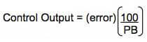
Proportional controller: With proportional band, the controller output changes in “proportion” to the error between process variable and set point. The amplitude of the change is adjustable from 1% to 999.9%. This range may differ from vendor to vendor.

Proportional Band

Refer to Figure 1 below. The example of a temperature controller shows a proportional band setting of 5%.
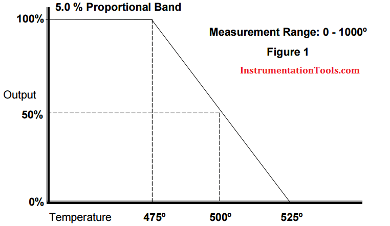
Proportional Band example

Set point = 500°
Measurement range = 0-1000°
5% PB = 5% of 1000° = 50°
100% output at 475° (2.5% of 1000°)
0% output at 525° (2.5% of 1000°)

If the process variable equals the set point (500°), there is a 50% output. As the temperature decreases, the proportional band increases the output linearly toward 100% as the temperature falls toward 475°. The output decreases below 50% as the temperature rises toward 525°.

In this example, a small change in temperature provides a large change in output. If the setting is too small for the process dynamics, oscillations will occur and will not settle at set point. A large PB setting makes the controller act sluggish and will not respond adequately to upsets.

Since proportional control does not incorporate the time that the error has existed, there will always be an offset from set point.

Typically, flow or pressure controllers have a much larger proportional setting due to a possible narrower measurement range and fast process reaction to a change in the control output.

OFFSET

Whenever a process load change occurs and makes the process deviate from the steady state condition, the controller will respond and limit the excursion of the controlled variable.

For this to occur, and error must develop, because, for the controller output (CO) to be at a value other than the bias (b), there must be an error, and so, if the load change continues, so will the error.

This sustained error due to the existence of a continuing process load change in a process controlled by a proportional only controller is termed offset.

Control systems may also experience changes in setpoint, which are called setpoint load changes. Integrating and nonintegrating processes respond differently to these setpoint load changes under proportional control.

Non-integrating processes will experience offsets due to setpoint lead changes while integrating processes will not.

Integral controller will be used to reduce this offset error. click here to the article.

Don't Miss Our Updates
Be the first to get exclusive content straight to your email.
We promise not to spam you. You can unsubscribe at any time.
Invalid email address
You've successfully subscribed !

Continue Reading

Alarm Simulator for Annunciator Logic
Vendor Document for Project Systems Architecture
DCS
Instrument Loop Test Requirements and Operation Procedures
Foundation Fieldbus Installation and Best Practices
Loop Check of 4-20mA or HART Transmitters
Share This Article
Facebook Whatsapp Whatsapp LinkedIn Copy Link
Share
2 Comments
  • Richard (Dick) Caro, CAP, ISA Life Fellow says:
    March 7, 2017 at 3:46 am

    It is a matter of mathematics. When a Proportional-only controller is switched from Manual to Automatic, we would like for the process to not suddenly change – we call that bumpless transfer. Before the operator makes that switch, the control valve was adjusted by the operator to a position that is satisfactory to running the process. The equation for Proportional-only control is:

    M = Kp * (PV-SP) + B
    where: M is the control valve position
    Kp is the Proportional tuning constant
    PV is the process variable
    SP is the setpoint
    B is a bias

    When the switch to Auto occurs, in order for bumpless transfer to occur, the B term will have a value of the control valve position since by definition, SP=PV, or zero error.

    Then, for any other value of PV, there will be an error value, and a new value of M will be calculated, but since the B term was set for the initial conditions, M will not be at the right value for zero error.

    Reply
  • Soumitra Ghosh says:
    March 7, 2017 at 6:59 am

    Proportional controller works purely on existing error signal.So you always need a measurable error signal to generate an effective output signal.Therefore, there will always be an offset exists in control variable. By increasing gain one can reduce the offset,but this also leads to system oscillation.

    Reply

Leave a Reply Cancel reply

Your email address will not be published. Required fields are marked *

Stay Connected

128.3kFollowersLike
69.1kFollowersFollow
210kSubscribersSubscribe
38kFollowersFollow

Categories

Explore More

Control Systems Interview Questions & Answers
ICS Control System Security
Purpose of Gateways, Bridges & Routers in Networking
Basics of Motion Controllers
Basics for CAN Bus Protocol – Controller Area Network
Process Control Fundamentals
Layer-2 and Layer-3 Network Switches
What is a Network Connector? – Types of Connectors

Keep Learning

Building Management System

Building Management System

Temperature Control System Example

Chemical Reactor Temperature Control System

Analog inputs in library

Design Process Graphics in Factory Talk View Studio with an Analog Input

Electrical Ground Loop

How to Solve Electrical Ground Loop Problems?

Difference Between Single Pair Ethernet and Traditional Ethernet

Difference Between Single Pair Ethernet and Traditional Ethernet

Basic Concepts of the Safety Relay

Basic Concepts of the Safety Relay

Control Room Design Guidelines

Control Room Design Guidelines

Augmented Reality and Virtual Reality in Industrial Automation

Augmented Reality and Virtual Reality in Industrial Automation

Learn More

Burst Transformers Root Cause Analysis

Root Cause Analysis – Burst Transformers and 11 kV Input Breakers

What is a Servo Valve?

What is a Servo Valve? – Principle and Advantages

Circulating Pump

What is a Circulating Pump?

Butterfly Valve Failure caused Fire

Butterfly Valve Failure Caused Serious vicinity Heavy Fire

Time Response Analysis

Effect of Adding a Zero to a System – II

PLC engineering software

How to Download GX Works? Mitsubishi PLC Software

Best Engineering Mobile Apps

Best Engineering Mobile Apps on Google Play & App Store

Siemens PLC Math Instructions

Siemens PLC Mathematics Instructions

Menu

  • About
  • Privacy Policy
  • Copyright

Quick Links

  • Learn PLC
  • Helping Hand
  • Part Time Job

YouTube Subscribe

Follow US
All rights reserved. Reproduction in whole or in part without written permission is prohibited.
Welcome Back!

Sign in to your account

Username or Email Address
Password

Lost your password?