One important part of Instrumentation & Control (I&C) Engineers’ roles and responsibilities during the whole lifecycle of process plant projects (and especially during Detail Design Engineering) is related to the design and implementation of required control and safety systems.
Instrumentation & Control
Systems Architecture as a Main Part of I&C Engineers Roles and Responsibilities:
As shown in Figure-1 (as the extraction of the I&C Roles and Documentations Model) I&C Engineers shall study the project requirements via different project inputs and understand the overall I&C requirements concepts (considerations) for proceeding with the activities and documentation required for the project.
(For the whole I&C Engineers roles and responsibilities model please refer to mentioned Reference).
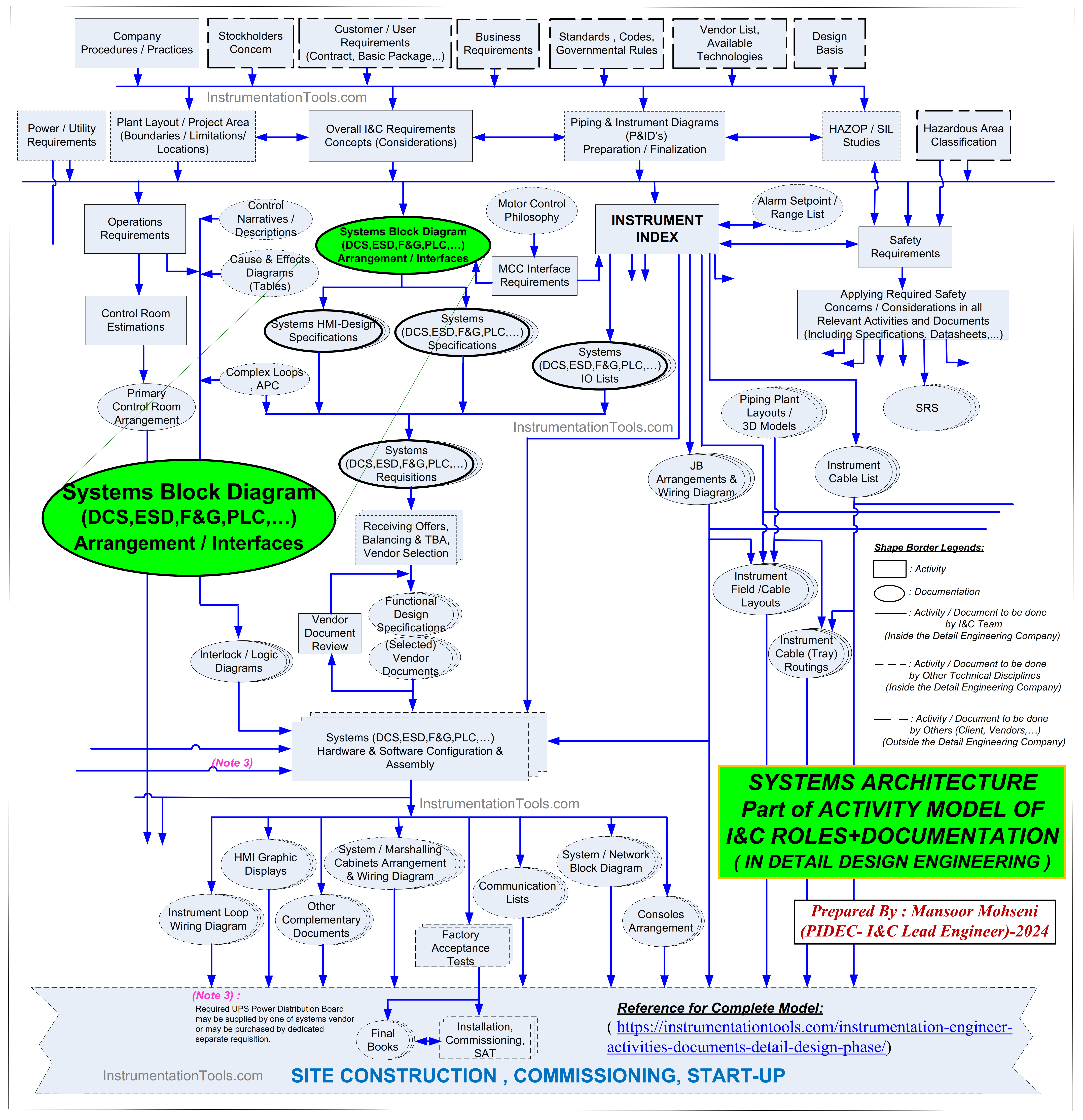
Figure-1: Systems Architecture as a Main Part of I&C Engineers Roles and Responsibilities
After getting project requirements considerations, I&C Engineers are ready to define project control philosophy and accordingly shall prepare suitable model for definition of required control and safety systems.
Systems Architecture Diagram
Usually they shall prepare one block diagram to define the overall requirements due to all project control and safety systems. Such diagram may have different names in different engineering companies like “SYSTEMS ARCHITECURE DIAGRAM” or “CONTROL SYSTEMS BLOCK DIAGRAM”.
Since the combination of some systems can be considered as “system of systems” or simply as a complex system (and may be due to simplifying document title text) usually instead of SYSTEMS in document title the word SYSTEM is used i.e. “SYSTEM ARCHITECURE DIAGRAM” or “CONTROL SYSTEM BLOCK DIAGRAM”.
Also since SAFETY SYSTEMS are (some systems) similar to CONTROL SYTEMS, but to control (and protect) the hazards and risks of process plant, they can be considered under the name of CONTROL SYSTEMS too, and so in order to reduce the document title, SAFETY SYSTEMS is deleted from document title. Regardless of document title, such document shows different parts of control systems as some blocks with relevant connections.
Control System Block Diagram
Here it shall be noticed that the title “CONTROL SYSTEM BLOCK DIAGRAM” document in industrial projects is used for different concepts versus to similar titles in scientific studies or books.
Although in both cases the blocks are used to show different parts of control system, but in scientific studies and books, such blocks mainly are used as functional or mathematical models (or concepts) while in industrial projects (system documents) such blocks are used to show different physical (hardware) components of project systems.
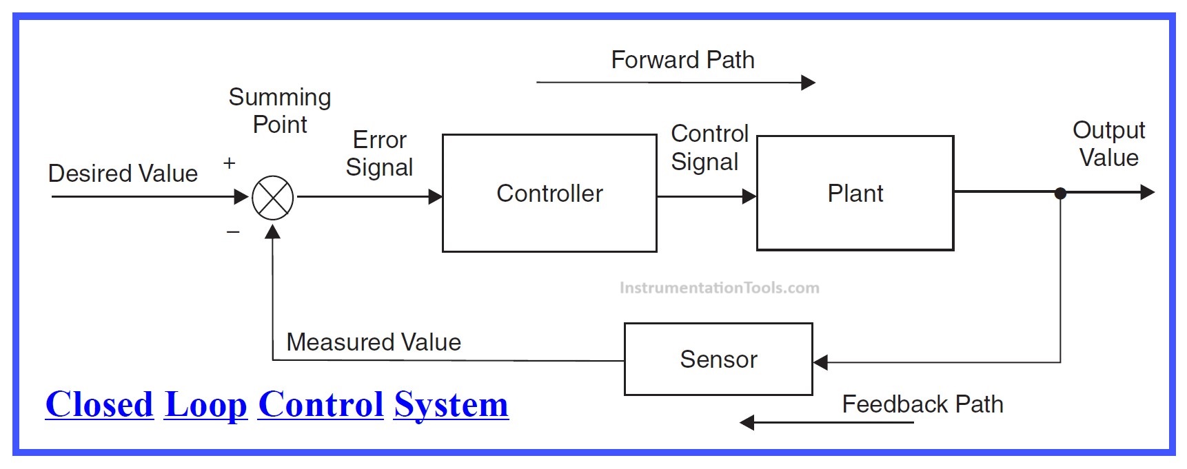
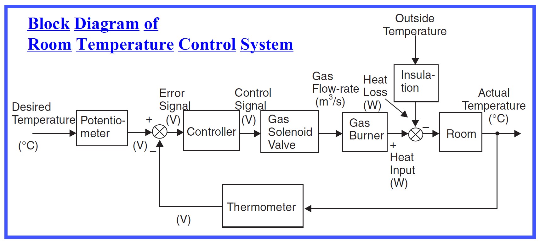
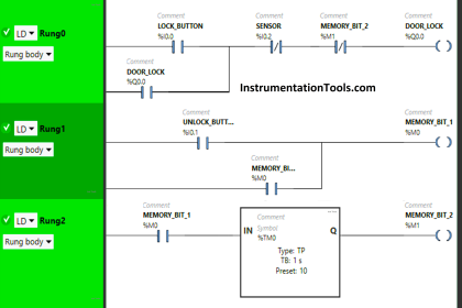
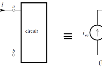
Figure-2: Samples of Control System Block Diagram in scientific studies and books
Another difference may be refer to which more exact blocks used in scientific studies and books (so that each block may be defined as mathematical transfer function), while in design document of industrial projects (Control System Block Diagram), the blocks are used just as schematic and the shown symbols may be not exactly equivalent to real hardware system (See Figure-2).
In fact in design document of industrial project, each block is used just to make some reference to document viewer in order to imagine the probable or possible actual equivalent hardware.
So simply we can say, in Industrial Projects a kind of document or diagram is used to show different parts of project actual systems (system of systems), which may have different titles in detail engineering companies (SYSTEM ARCHITECTURE or CONTROL SYSTEM BLOCK DIAGRAM).
Design Document
After above introduction, now we can review the Design Document for SYSTEM ARCHITECTURE which is prepared in detail engineering company, and it can be defined as a document which illustrates the architecture of the plant control systems and the interface between systems required for the overall operation (control and safety) of a process plant.
Figure-3 shows a sample of schematic template used for SYSTEM ARCHITECTURE DIAGRAM in detail design engineering company while by considering it we will review some items for preparation of this document and some main information which shall be included in such document.
Figure-3: Sample of Control System Block Diagram Template in Industrial Project (Sample Schematic Template for System(s) Architecture Diagram)
The level of functionality, complexity, and safety of a plant determines which Control Systems are needed. This could include a process control system, safety instrumented system, HIPPS, Fire & Gas system, and other control and safety systems dedicated to different packages or unit parts of the process plant. These items shall be shown on diagram document.
System Architecture Diagram Document
The SYSTEM ARCHITECTURE diagram document shall include all main functional areas of the plant. As Figure-3 shows such main areas may be distinguished as : Field, Aux/Cabinet Room, Control (Operator) Room, Engineering Room, Manager & Supervisory Room, Electrical Substations (MCC Rooms), UPS & Battery Room, Offsite/ Other Plants which have interfacings with subjected project.
Further to mentioned areas, some other areas may be added to template (of SYSTEM ARCHITECTURE) due to subjected project requirements like: Compressor House, Material Handling Area, Warehouses, Loading / Unloading Area ,… The System Architecture must clearly define the locations, including the main locations, remote I/O locations, indoor/outdoor locations, and the limit between the control room and the building.
Symbols and Abbreviations
The symbols which are shown on diagram are just schematic/ symbolic and are not based on real equipment or situations. However by using symbol size and quantity facilities, may make some distinguishes between different similar items.
Furthermore some symbols are shown just as head of some similar collections of items. Although for showing the blocks, simple shapes (Square, Rectangle, Triangle,…) can be used, but if the block shape are selected from default icons or prepared shapes which have intellectual connection with the block function, It will be more helpful for document reviewer (but notice that , extra use of complex icons or shapes may have reverse result or busy diagram document).
The Symbols and Abbreviations shall be clearly defined on SYSTEM ARCHITECTURE diagram (or attachment sheets of this document). Furthermore any special case (required standard) or important consideration points shall be mentioned on this document as note texts.
It is very important to notice that SYSTEM ARCHITECTURE is not the document to show all the details of the subjected project and sometimes to reduce the complexity of document and simplifying the relation of shown blocks, some items may be not shown (or withdrawn), but by mentioning some references or extra notes, viewers of document will be informed for any further cares or studies.
Of course the Field Area will contain a big amount of instrument items which cannot be shown on SYSTEM ARCHITECTURE diagram, but by using suitable symbols, the main characteristics of such items shall be illustrated.
For example some of such characteristics may be distinguished as : Conventional IO’s / Fieldbus IO’s, Analog/ Digital Signals, IS / Non-IS Instruments, Safety / Control (Usual) Instruments, Local Panels, Special Items, Field Control Panels.
Supervisory Level Equipment
SYSTEM ARCHITECTURE diagram shall also show supervisory level equipment like operator’s workstations, engineering workstations, Extra required facilities for systems (including HMI Server, OPC Server, Historian Server, Sequence of Event Recorder, Advanced Process Control (APC) Station, …) , Hardwired Human System Interfaces ( like ESD Hardwired Console/ Panel (push buttons and lamps), Alarm Annunciators, Fire & Gas Matrix or MIMICS, …), Packages Monitoring Facilities (like Machine Monitoring Systems, Condition Monitoring System, Tank Gauging System, Analyzer Workstations, …) ,….
Higher levels of automation monitoring stations or facilities also shall be shown, like Management Information System (MIS), Production Management System, Asset Management System, Maintenance Management System.
SYSTEM ARCHITECTURE diagram further to show different parts of considered control systems, shall show the main interface connections or communication of these blocks too. Additionally, the major control, Ethernet, and communication cables and Network Equipment shall be displayed.
Also for some special cases the considered hardwired signals (cables) shall be clarified too. For simple SYSTEM ARCHITECTURE diagram, showing communications and networks may be applicable but for complex or big system, it is not possible to show all important communications and networks.
In such cases complementary diagram shall be provided to show such requirements too, as shown on Figure-4 as an example of a realistic industrial project. If the structure format of such complementary document was created based on the SYSTEM ARCHITECTURE diagram, it may help to better understand the conjunctions of both documents.
Sometimes for preparation of SYSTEM ARCHITECTURE documents and different connections of shown blocks, I&C engineers use some termination symbols and codes at both destination points of connection line, and by this method many lines are not shown and so the diagram may be less busy (See Figure-5).
Process Plant System Architecture
The Figure-3 is sample of SYSTEM ARCHITECTURE for one dedicated process plant, and on the other hand, if the subjected project may contain different process plants, it would be better to provide one SYSTEM ARCHITECTURE per each plant further to one simplified total overview of functional relations of such process plants. However if the different parts of process plants of subjected project are limited, and where possible to show all project systems in one SYSTEM ARCHITECTURE diagram, may be more useful.
Generally the SYSTEM ARCHITECTURE document shall be prepared as black and white format and every distinction between similar items shall be done by suitable visionary icons or legends without any color differences.
However if further to caring such method or rule for distinguishing items, the color facility is used, such document (and accordingly Network Communication Diagram) will be more useful and understandable (as figures 3 and 4 show) while by black and white printing the document no information will be missed.
For showing package control and safety systems in SYSTEM ARCITECTURE diagram, simple blocks (with possibly some limited important items) can be shown, while the detail of such items may be referred to dedicated prepared documents.
Figure-4: Sample of Considered Communication and Networks for a Typical Industrial Project (Complementary Design Document to System Architecture Diagram)
Issue Reasons and Results of Systems Architecture
SYSTEM ARCHITECTURE Diagram document is issued by I&C Engineer team at early stage of detail design engineering phase of Industrial Project to clarify the considered control philosophy on required systems and relevant communications (based on project requirements) to inform all stakeholders and responsible persons accordingly.
The issue reasons of this document for mentioned specialists may be to inform them, get their approvals, or asking them to use it as basis of their future actions and documents. Client and other responsible technical (discipline) specialists use such document for information and understanding the considered items or even making comments for any changes, while system vendors will use it as basis of their offers or future designs on project required items. However this document may be the core document of I&C team for their future activities and documentations too.
Design Engineering
SYSTEM ARCHITECTURE Diagram document is issued at early stage of detail design engineering phase of Industrial Project (based on project inputs and primary system architecture prepared at Basic Design Engineering phase ), but it may be completed (or changed) during later stages of this phase due to finding some limitations or better solutions (on blocks and communications implementations).
Understanding the project requirement inputs and accordingly prepare control philosophy and SYSTEM ARCHITECTURE DIAGRAM document needs a competence I&C Engineer (or team) with a good practice and experience (resume) further to required knowledge and skills. Such activities may seem easy but in fact they are very complicated and competence I&C Engineer by doing that will provide simpler approaches and conditions for I&C team on future activities and documentations.
SYSTEM ARCHITECTURE DIAGRAM document is used as basis for requisitions on Control & Safety Systems (including PLC, DCS, ESD, FGS, …) and if it is provided properly and by suitable format, the vendors of such systems can understand it easily and they will provide their offers accordingly. By such uniform consideration, the comparison of such vendor’s offers during Technical Bid Analysis/Evaluation (TBA/TBA) will be greatly easier.
Sample Control System Diagram for Industrial Project
By reviewing one realistic SYSTEM ARCHITECTURE DIAGRAM document for a complex process plant (industrial project) we may found how complexity of considering different systems and their relations will be understandable and how such document may help different specialists to have similar foundations for their activities (DCS, ESD, Packages Control Panels, …) . Figure-5 is a sample of such realistic document.
Figure-5: Sample of Realistic Control System Block Diagram for Industrial Project (System Architecture Diagram Provided in Detail Design Engineering Company)
References:
- I&C Engineer Roles & Responsibilities
- Instrumentation Engineer Activities & Documents
- Instrumentation and Control Project Packages