The Belt Conveyor Weighing System continuously measures the weight of bulk material as it moves along a conveyor belt.
A belt scale system is also called a conveyor belt scale or conveyor belt weighing system.
Belt Conveyor Weighing
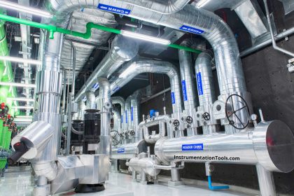
Generally, for more accuracy, we use a Multi-idler belt scale system. Multi-idler belt scale system is heavy duty, high-accuracy full-frame multi-idler system used for Fertilizer plants (To measure the Bulk Urea Weight), cement plants (To measure the Raw material and final product weight on bulk conveyor), and power plants to measure the weight of fuel (Coal etc.).
Mostly in the Urea Fertilizer Plant, this belt scale assembly is installed at the main bulk conveyor which receives Urea from the Urea Plant and sends it to the Bagging Plant. Also in the Coal Based Power Plant, this belt scale assembly is installed at the outlet of the Coal Crusher plant.
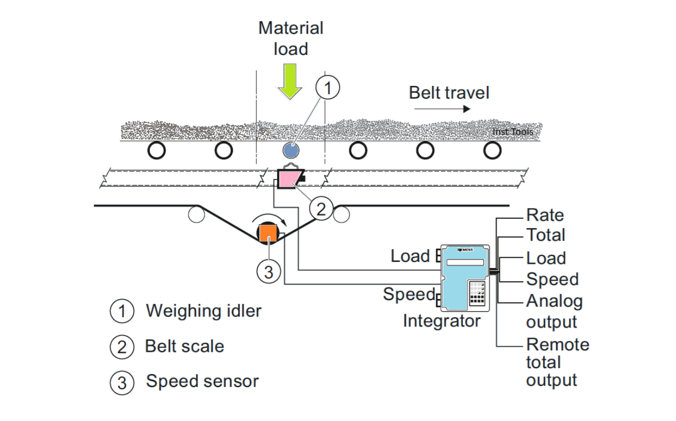
Important Components of Belt Scale System
Most Belt Scale system consists of Three Main components, These components are listed below:-
- The Weigh Bridge or The Scale Carriage.
- The Belt Speed Sensor.
- The Electronic Unit i.e. Integrator.
The Weigh Bridge
Each component of the Belt scale system serves a distinct function in the process of accurately weighing material moving on the belt.
The Weigh Bridge assembly is the primary belt load sensor mounting under the carrying side of the belt on the stringer. It supports weighing idlers and generates an electrical output proportional to belt loading with the help of the load cell.
These load cells are constructed with SS material and have an IP67 rating for dust and liquid protection and a temperature range between 0 -70 Degrees Celsius. These load cells fitted just below of weigh bridge frame. The Load cell with tension mounting is freely floating to avoid errors due to side forces from uneven distribution of material on the belt and uneven force impact during the off-center position of the belt.
The deflection of the load cell is only 0.10 mm to -0.15 mm which ensures that errors due to change in belt tension are contained within acceptable limits. The weigh bridge design and construction are such that in contribute to the conveyor stringer section modulus in the scale area and provide additional stiffness and supports to minimize stringer deflection.
Stringer – Stringers are horizontal support structures that run parallel to the conveyor belt and provide stability and support for the conveyor system. Stringers serve as the mounting base for the belt scales system.
Load Cell Used in Weigh Bridge –Tension-type sealed stainless steel constructed load cells are used which have 100 % Overload Protection and are freely mounted at both ends to avoid transverse force errors.
Also, these Load cells have few properties –
Electrical Properties:
- Insulation Resistance @50VDC >= 5000 Mega ohm
- Input Resistance = 350 to 450 ohms
- Output Resistance = 320 to 360 ohms
- Excitation Voltage =5-15 VDC
Specification:
- IP rating – IP67
- Full-Scale Output (mV/V)- 2 to 2.002 or 3.00 to 3.003
- Zero Balance – <= +- 2 (%FS)
- Combined Error- <= 0.05 (%FS)
- Hysteresis- <= 0.05 (%FS)
Some Important Features of Weigh Bridge:
Some most important features of the Weigh Bridge are listed below –
- Weigh Bridge has no moving or wearing parts.
- The Weigh Bridge has a Stainless Steel frame construction.
- Weigh Bridge has a slim profile which minimizes material build-up & Zero Drift property.
- The Weigh Bridge has a total deflection of the weigh idler less than 0.1mm.
- The Weigh Scale has Intrinsic stiffness and support to the conveyor in the scale frame Area for better accuracy.
The Belt Speed Sensor
A speed sensor is mechanically coupled to the tail pulley or large-diameter idler and provides a stream of pulses each representing a unit of belt travel. For high accuracy, the belt speed must not to too fluctuating.
So much fluctuation will affect the accuracy of the Belt Scale. For Example- If Our Belt Speed is 1.5 meters/sec and fluctuates between 1.3 to 1.6 m/sec then it is okay but the range go beyond this will definitely affect the accuracy.
Important Point to note for Speed Sensor:
- Speed sensor to be driven by conveyor tail pulley shaft or by special return roller.
- Do not rigid mount Speed sensor.
- Speed sensor assembly must be directly coupled to the driving shaft. Do not drive with chains, Belts, Gears, etc.
- Never Mount a Speed sensor on a motor-driven pulley.
- Attach the restraining arm to the speed sensor with two 8mmx30mm long bolts.
The Electronic Unit i.e. Integrator
In the belt scale system, the integrator is an electronic system that receives a Load cell signal (mVolt), Belt speed (meter/second) and Belt length(meter) are predefined in the system. After calculation and compensation, this Integrator shows the Material flow value in our required (From Available unit in integrator) i.e. Ton/Hour or any other unit.
The integrator is a micro-computer-driven instrument designed for easy operation and calibration of the Belt Scale System. By suitable processing of two input signals i.e. weight of the material and Belt Speed (Meter/second), the integrator delivers visible and electrical output representing the rate of material movement and visible and electrical output representing the total amount of material that has passed the weighbridge.
For a remote indication of Flow, we have two options available –
- Relay output to drive remote counter.
- A 4-20 mA current signal represents the rate of flow.
In general practice, we used a 4-20 mA signal to show the rate of flow in the control room.
A few most important points must be considered during the installation of the Integrator unit:
- Always use flexible conduit for the load cell cable.
- Mounting of the Junction box should be on the Conveyor or adjacent wall within the required distance.
- The integrator must be mounted within a maximum 70-meter range of the Weigh Bridge system. For distances greater than 70 meters, the 6-wire connection should be used for better accuracy and performance of the system.
After every replacement of the Load cell, we must do Belt Scale system Zero Calibration, Span Calibration, and Material testing during the belt running condition, and during the material testing take a time duration.
Suppose 60 minutes or more for better accuracy setting and cross check belt scale Integrator 60 minutes flow and manually i.e. for that 60 minutes fill any buffer hopper and note that hopper level during starting and ending of filling. Also, if found any deviation in material then fill that difference into integrator.
Conclusion
Now after the above discussion, we can clearly say that belt scales offer accurate, efficient, and streamlined weighing solutions for bulk material handling (Urea, etc.) operations. Unlike any other traditional methods where materials need to be removed from one area, weighed, and then transported to another, belt scales allow in-line weighing. This streamlines the process, saving time, effort, and money. Also, it plays a vital role in monitoring the production of any plant, also helps to fulfill the weight & Scale norms.