General Specification is a deliverable prepared by Instrumentation and Control (I&C) Engineers to define minimum requirements for designing Instrumentation in EPC or EPCM Companies. For each parameter (like Flow, Temperature, level, pressure), A separate document is prepared.
Instrumentation General Specifications
We shall first see the typical structure of the Document.
Typical Structure
- Table of Contents – The Table of Contents should cover the topics included in the specification with their sub-chapters and page numbers.
- Purpose – The purpose of the specification should be clearly defined.
- Scope – The scope should be clearly defined.
- Technical requirements – Technical requirements should cover the Technical content as defined in the “Purpose” and “Scope” divided into sub-chapters and their sub-topics.
- Reference Standards – Reference Standards I.e. Codes and Standards referred for preparing the specification should be listed.
- Inspection & Testing requirements – ITP requirements shall be listed or attached with the specification.
- Vendor Data Requirements – VDR shall be attached with the specification.
The data listed in the standard specification shall be the basis for preparing RFQ datasheets for Vendors to quote with a suitable Model no.
Flow Instruments General Specification
Flow Instrument selection – Standard instrument type preference and applicability as per service and process data shall be specified.
Instrument type-specific requirements shall be specified e.g.
Orifice plate type – Concentric (Standard), Eccentric (two-phase fluids), Segmental (liquids containing large amounts of solid, or Slurries), Quadrant edge (highly viscous liquids with Reynolds number 2000 to 10000), Conical entrance (highly viscous liquids with low Reynolds number 80 to 2000).
Orifice plate taps – Flange taps shall be used for line sizes 2” to 12“ while D-D/2 taps shall be used for line sizes 14″ and above. Orifice flanges used at pressure ratings up to 600 lb. shall be tapped ½” female NPT; for 900 lb. and above – ¾” female NPT
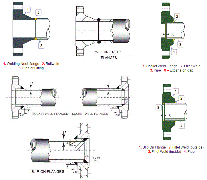
Orifice plate flanges – Type (e.g. Weld neck per ANSI B16.36) &Minimum flange rating (300#).
Orifice plate Material – SS316 minimum.
Orifice flange, gaskets, bolts & nuts – Material shall be as per the relevant Piping material Specification.
Vent / Drain hole requirement
Sizing criteria – Standard to be specified for Sizing of Orifice plates e.g. ISO-5167 and AGA Report 3 / R.W. Miller. Meter max, differential ranges allowed to be specified.
Beta ratio – To be specified.
Orifice plate dimensions – Standard to be specified e.g. BS-1042, Part 1.
Upstream & downstream straight length – Standard to be specified e.g. ISO-5167, AGA Report 3
Jack screw requirement – Flanges larger than 3″ shall have a pair of jack-screws.
Orifice plate dimensions – Standard to be specified e.g. BS-1042, Part 1.
Upstream & downstream straight length – Standard to be specified e.g. ISO-5167, AGA Report 3
Jack screw requirement – Flanges larger than 3″ shall have a pair of jack-screws.
Orifice bore size – Minimum size to be specified e.g. 0.125”.
Level Instrument Specification
Level Instrument selection – Instrument type applicability as per service and process data shall be specified:
DP type LT – General applications above center to center (C-C) of 1219 mm.
Displacer type LT – Displacer can be used for C-C up to 1219 mm mainly for Interface measurement.
Other types – Radar, Ultrasonic, Nucleonic, Capacitance, Conductivity, and Magnetostrictive type shall be used as necessitated by application requirements.
Pressure Instrument Specification
Pressure Instrument selection – Standard instrument type preference and applicability as per service and process data shall be specified.
Instrument type-specific requirements shall be specified e.g.
1. Pressure / DP sensor type – e.g. Electronic Capacitance type.
2. Transmitter type – 4-20mA HART, 2-Wire or FF to be specified.
3. Hazardous area classification / Weatherproofing – Certification e.g. Flameproof or intrinsically safe & Weatherproof (IP-65).
4. Body material, Element material – SS316 Minimum.
5. Overpressure rating – At least 1.5 times the maximum working pressure.
6. Integral digital LCD display & External Zero adjustment.
7. EMC (electromagnetic compatibility requirements) – As per IEC 60801. Rangeability: 100:1
8. Accuracy: +/- 0.1% of span for a rangeability of 1:10.
9. Range selection – Operating pressure shall be read at no greater than 75% of the calibrated range for steady pressures. For fluctuating services, the normal pressure shall be read at 60% of the range.
10. Process connection – ½” NPT(F).
11. Diaphragm seal element with capillary – Shall be used for congealing, corrosive, and highly viscous services at high operating temperatures.
12. Manifold – Integral two valve/ three-valve/ five-valve manifold as per the specific requirements shall be used.
Temperature Instrument Specification
Temperature Instrument selection – Instrument type applicability as per service and process data shall be specified.
Thermocouples or Resistance temperature detectors (RTD) shall be used depending on the process requirements.
Thermocouple
- Code – Thermocouples shall comply with ANSI MC 96.1 and shall be as per IEC-60584-2 / IS -7358.
- Element – Magnesium oxide (MgO) filled, ungrounded, and K-type in general.
- Wire size – 18 AWG for single and 20 AWG for duplex thermocouples, in general.
- Sheath material – 316 SS as a minimum. Inconel 600 sheath for temperatures greater than 600°C.
RTD
- Element – Platinum element, 3-wire type with 100 Ohms resistance at 0°C calibrated as per IEC 60751 / DIN 43760.
- Temperature range – RTDs shall be used for temp. range -200 to 650°C.
- Accuracy – 0.25%, Class ‘A’ / Class ‘1’ tolerance as per IEC 60751 / 60584-2.
Control Valve Specification
Control valve selection – Instrument type applicability as per service and process data shall be specified.
Control valve type – Globe type is preferred. Butterfly, plug, angle, or 3 way, etc. shall be selected as per service requirements.
Control valve body – Flanged control valves shall be used. Body material, body rating shall be as per piping specifications as a minimum. The minimum control valve body size shall be 1″ in general.
Noise level – The noise level shall be less than or equal to 85 dBA SPL (Sound Pressure Level).
Leakage class – Class IV or V. More info here.
Sizing – Control valve sizing shall be carried out as per ISA S75.01.
Packing – Packing shall be PTFE on liquid and gas service up to 200°C and Grafoil for 200°C and above.
Trim material – SS316 minimum.
Trim characteristics – Equal percentage type, in general. More info here.
Body Construction – Single seated with top guiding for low DP applications and cage guided for high-pressure drop applications, in general.
Severe Service Valve Selection
Hardened plug and seat rings (Stellite 6 or Colomonoy coated) shall be selected for
- Corrosive services.
- Erosive services (Slurries).
- Steam services with DP>5 bar
- Services with DP >10 bar.
- Flashing or Cavitating fluids.
- Anti-cavitation trim shall be selected in case of cavitation.
Interest to add any further points? Share with us through below comments section.
Author: Kalpit Patel
Read Next:
- Instrumentation Design
- DCS Wiring Schemes
- Control Valve Accessories
- Intrinsic Safe Calculation
- Inter Discipline Check