The instrumentation architecture consists of field instruments, multi-core cables, junction boxes, marshalling, and system cabinets.
Instrumentation Architecture
Field Instruments
In industries we use many types of field instruments for the monitoring and controlling of process variables like temperature, pressure, flow, level, etc.
The common types of field instruments are pressure transmitters, level transmitters, flow transmitters, temperature transmitters, shutdown valves (on/off valves), control valves.
The transmitters and control valves are installed as per the P&ID design. We have thousands of instruments in a medium size plant.
All these instruments need to be connected to the respective PLC or DCS control systems.
Junction Box
Practically its not possible to lay individual cables from the each instrument to the control system.
So we introduced a intermediate place where we connect certain number of instruments and then we lay one single cable to connect these instruments to the control system.
This intermediate place is called “Junction Box“.
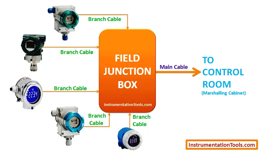
So instead of laying 20 different cables from field to control system, we need 1 main cable with a junction box.
Similarly as per the plant design, certain number of instruments are grouped as per their category and connected to their respective junction box. The number of junction boxes depends on the total number of instruments and their categorization.
Example
For example, 20 different instruments are connected to one junction box. so we lay 20 individual one pair cables (these cables are called as branch cables) from each instrument to the junction box.
And we need 20 pair or more than 20 pair cable to connect from junction box to control system (this cable is called as main cable or home run cable).
Usually we left some spare pairs in the main cable, so in this example we consider a 24 pair main cable.
Marshalling Cabinet
Consider we have 100 junction boxes in the field. So a total of 100 main cables will be layed from the junction boxes to the control system.
Ideally all the instruments need to connected to the central processing unit (CPU) of a PLC or DCS control system.
With the latest technology, all the Input Output modules, processor units are available in compact size.
Practically, its not possible to connect and terminate these 100 main cables to the respective input output modules, and it will be very difficult to troubleshoot if any problems occur.
So we introduced another intermediate place for connecting all these 100 main cables.
This place is called as “Marshalling Cabinet” or “Marshalling Panel”.
The main cables are terminated in the marshalling cabinet. The marshalling cabinet may also equip with fuses, barriers, external power supply units, etc.
The number of marshalling cabinets will vary and it depends on the number of instruments, number of junction boxes, number of cables, etc.
The main cables cross-sectional area will be 1.5 Sqmm, 2.5 Sqmm, etc. Depends on your plant design.
If you have limited number of instruments/junction boxes/main cables then the marshalling cabinet may be not considered inorder to reduce the project costs.
In some cases, you may not need the marshalling cabinets.
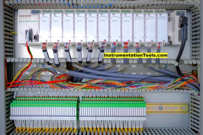
System Cabinet
System cabinet is the heart of our control system. System cabinet equips with all the major electronic parts like Power supply units, Central processing units (CPU), Analog input modules, Analog output modules, Digital input modules, Digital output modules, communication modules, etc.
From our above discussing, we connected our field instruments in the marshalling cabinet.
Now we have to connect field instruments from the marshalling cabinet to the system cabinet.
Here we use prefab cables or internal cables for connecting between the marshalling cabinet and respective input and output modules.
These internal cables cross section area is very less like 0.5 sqmm, etc. It depends on the respective manufacturer and followed standard.
So with the help of these internal cables, all instruments will be connected in the system cabinet.
All these input and output modules, CPU, power supply units are mounted on a Printed Circuit board (PCB). With the help of PCB, all these modules are connected to the processor unit (CPU).
If you have more number of input and output modules, then more number of PCBs are required. In this case, some sort of communication modules are cables are used to connect these input output modules to the processor unit.
Finally, all input and output modules in the system cabinet are connected to the processor unit.
Also Read: PLC and Solenoid Valve Wiring
Operator Workstation
Then the processor units are connected to a router with the help of ethernet cables.
The operator workstations and engineering stations are also connected to the router via ethernet cables. so these are also finally connected to the processor unit via router.
The operator can read the field instruments values in the workstation.
The operator may also give commands using the graphical interface, then these commands will go the processor unit, where it will executes as per the designed logic.
Engineering workstation
The engineering workstation is used to configure or modify the processor logic as per the requirements.
The PLC or DCS engineering software and their respective licenses will be installed in the engineering workstation.
If you liked this article, then please subscribe to our YouTube Channel for PLC and SCADA video tutorials.
You can also follow us on Facebook and Twitter to receive daily updates.
Read Next:


In our refinery we had an accident so 3 cables are burned between junction box and cotrol room (20m) ,each cable have junction box ;so how to solve this problem;
1install nex junction box
2-Pull new cables 400 m*3 from control room to jonction box
What are the differences between operator room and engineering room?