The marshalling cabinet acts as an interface between the system cabinet and field junction boxes. The main cables are laid from the field junction boxes to the marshalling cabinet. The prefab cables from the system cabinet IO cards are also terminated in the marshalling cabinet.
The marshalling cabinet is used for the primary termination point for incoming field cables. Further, the other ends of wires are internally connected to system cabinets wherein the I/O modules and controllers are installed.
Marshalling Cabinet
In the below picture, there are three cabinets (or panels). The middle one is system cabinet and the left & right side are marshalling cabinets.
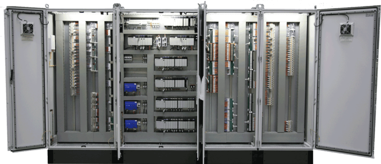
Image Courtesy: ITEC Engineering
As you can see from the below pictures, a conventional cabling work contains field inputs and output to a field junction box, then using a home run (Multipair/ Multi-core) cable to bring the signals from the field junction box to a marshalling panel in a control room / Instrument Technical Room, and then using cross-wiring to route the signals to respective termination assemblies.
The termination assemblies are connected via prefabricated cables to input/output modules in system cabinets.
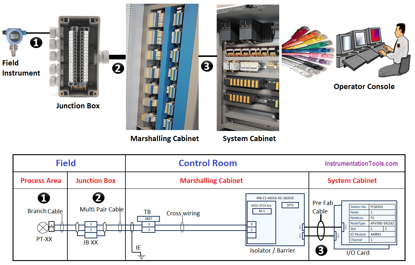
In simple terms, Marshalling cabinets are located between junction boxes and control system. Within the marshalling cabinets, field cables are connected and cross-wiring is performed to order the signals according to the I/O modules. In this way, it is possible to use prefabricated cables to interconnect the marshalling cabinets with the I/O modules.
Cabinet Types
- System Cabinet,
- Marshalling Cabinet,
- System cum marshalling cabinets,
- Electronic Marshalling
System Cabinet
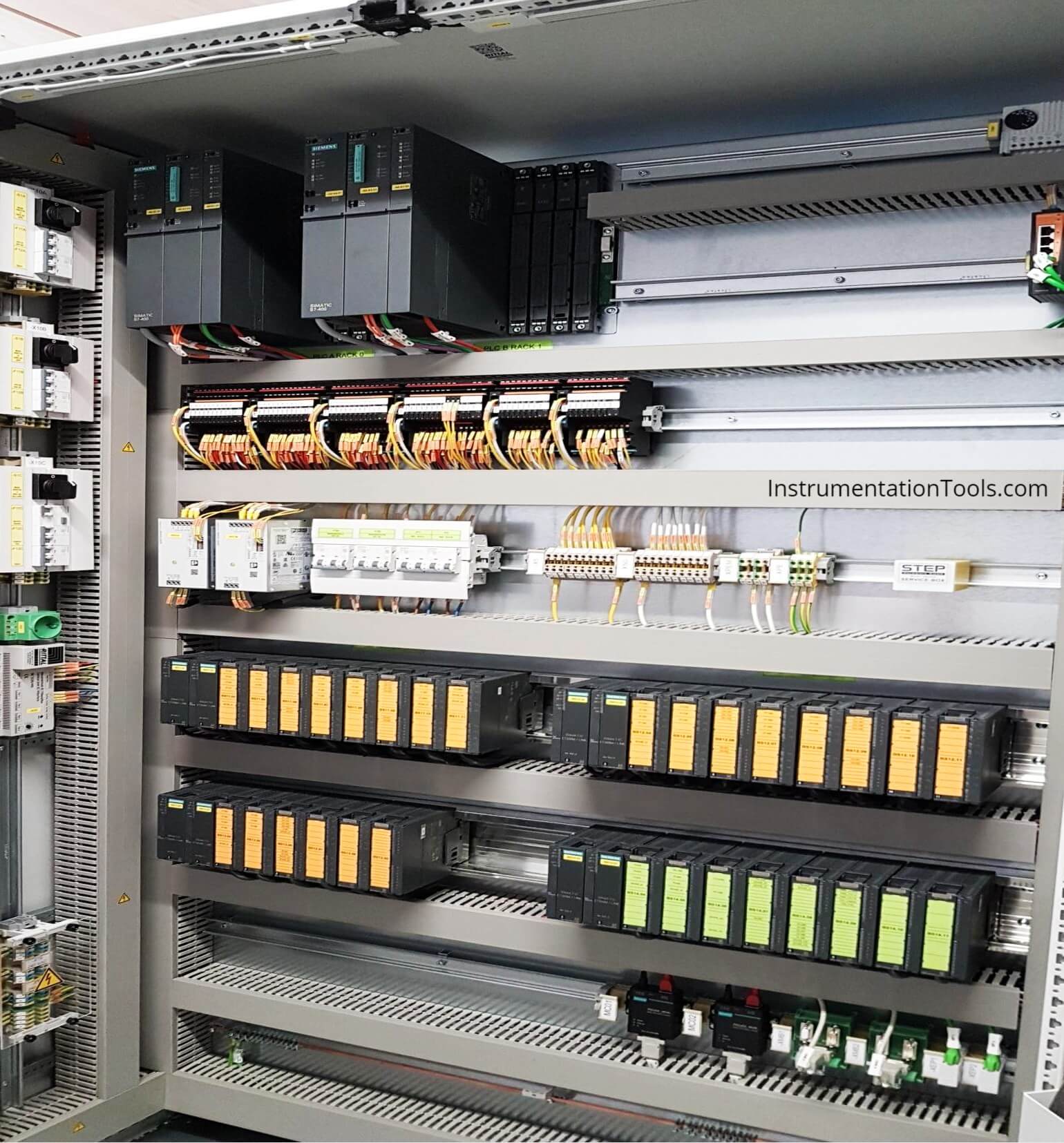
The major components of system cabinet are Controllers, I/O Modules, Communication Modules, Power supply modules, Diode Oring, etc.
Marshalling Cabinet
The major components of marshalling cabinet are Isolators/ Barrier, Relays, Terminal bocks for field home run cables, shield terminals, Terminal board for cross-wiring, Power supply modules, Diode Oring.
Dedicated marshalling cabinet is used for large I/O systems. When separate marshalling cabinets are used, these cabinets can be sent to site at the early phase of the project so that field cables are terminated.
Later when system cabinets are available then prefabricated cables are installed between marshalling and system cabinets. Separate cabinets have the advantage of staged Factory acceptance tests and staged delivery.
However, site work is involved to install the prefab cables. When FAT for system and Marshalling cabinet is done together then the connection between both cabinets is removed when shipped to the site.
Once delivered on-site, the connections between the marshalling and I/O terminals must be redone.
System cum Marshalling Cabinet
The major components of system cum marshalling cabinet are Controllers, I/O Modules, Power supply modules, Diode Oring, Isolators/ Barrier, Relays, Terminal bocks for field home run cables (main cables), shield terminals, Terminal board for cross-wiring.
This combined system cum marshalling cabinet is used for less I/O systems. Generally packaged control panels where fewer I/Os are involved there we can use the combined system and marshalling cabinets.
This kind of cabinets is supplied such that Controller, I/O modules, terminals, relays, barriers etc are installed in one cabinet. In this case, prefabricated cables are pre-installed.
Electronic Marshalling
Due to universal I/O concepts, field cables are directly connected to I/O modules itself. This eliminates the terminals blocks, cross-wiring and prefabricated cables what we saw in conventional marshalling cabinets. I/O type can be configured via software.
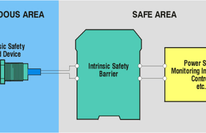
For intrinsically safe design, I/O card will have barrier slot for installation or related adaptors for field cable termination on I/O card itself.
This being the latest technology from control system suppliers which require fewer efforts at the site, require less fieldwork, and also require fewer cabinet footprints, has increased flexibility for spare channels.
Common Mistakes
Common mistakes that can be found during factory acceptance test or site loop checking activities.
- The wrong type of multi-pair/ multi-core cable used (individual shield, overall shields)
- Loose wire connections at terminals
- Improper lugging, ferrule and termination
- Improper selection of cable glands
- Wrong termination in Junction box/marshalling cabinets
- Wrong terminations in MCC interface (Common and Signal cable Interchanged)
- Wrong terminations (Polarity reversal in case of Analog signals)
- Improper Shield connection in Marshalling cabinet
- Wrong configuration in Field instrument (Upper range/lower range/ square root/ offset etc)
- Wrong channel configuration in the Control system (Active or passive or 3 wire signals)
- Wrong configuration at I/O module (Improper range or tag no mismatch)
- Fuse Blown fuse or no fuse inside the terminals or improper fuse rating or open terminals
- Wrong contact used in the field (NO/NC for digital signals)
- Wrong contact used for Digital output signals (Dry contact/wet contact)
- Interrogation Voltage found in dry contact
- Wrong connection in Relay, isolator and barrier or incompatible components
- Improper size of power supply module, MCB rating
- Internal wiring colour and wire size not as per requirement
- External power supply not considered for 4 wire instruments
Electronic Marshalling Cabinets
Points to take care during the design stage when using electronic marshalling cabinets:
Junction box grouping should be perfect so that cable can be terminated directly to I/O card same as junction box pair Sequence. Change in junction box grouping will have an impact on I/O assignment in DCS as electronic marshalling system does not have cross-wiring.
Some field cables might have both Redundant and non-redundant signals, it may not be possible to segregate redundant and non-redundant signal in I/O card. System vendor may need to use redundant I/O modules for such cases since control room side I/O termination is the mirror image of Junction box.
As far as possible, parallel equipment’s related I/Os should be separated in different cables for more available so that they can be assigned in different I/O cards. If, those signals are assigned in one multi-pair cable that will be terminated in one I/O card if that I/O card fails then that equipment is not available for control.
Spare philosophy of Channels should be agreed with the client and DCS vendor.
e.g. if 5 Pair field multi-pair cable has 3 I/O signals and 2 spares and then 3 Signals are directly connected to I/O card. Remaining 1 signal can be considered as wired spare to I/O card, also last 1 pair is left without any termination behind the I/O module or in the cable duct.
Since 4 I/O channels (3 I/O signals + 1 wired spare) are already occupied the next channel (5th channel) will be assigned to signal from another multi-pair cable.
Philosophy shall be agreed with the client at the earlier stage of design, once I/O assignment is frozen as described above then it would be very difficult to adopt a new philosophy.
Dedicated Marshalling Cabinets
Points to take care during the design stage when using dedicated marshalling cabinets:
- All the wires from field multi-pair/core cables should be terminated in marshalling cabinets. Change in cable type (e.g. 16 pair to 24 pair) would have increase terminals inside the marshalling cabinet.
- Change in junction box grouping will have little impact on cross-wiring. However, it will have no impact on I/O assignment.
- Parallel equipment, 2oo3 voting-related I/Os should be assigned in different I/O cards with help of cross-wiring.
- The number of main cables terminated in one cabinet should be reviewed properly for ease of maintenance. This is applicable for all type of marshalling/system cabinets.
- I/O allocation and marshalling cabinet should be based on the Controller segregation philosophy. This applies to all type of marshalling/system cabinets.
Cabinet construction-related details like dimension, colour, type of access, spare space, spare components, internal wire/duct colour, size, cable entry, smoke detection requirement, Ingress protection class, EMC requirement, etc should be considered as per project requirement.
Refer Nest loading article, for further details how I/Os are assigned.
System Cabinet Photo
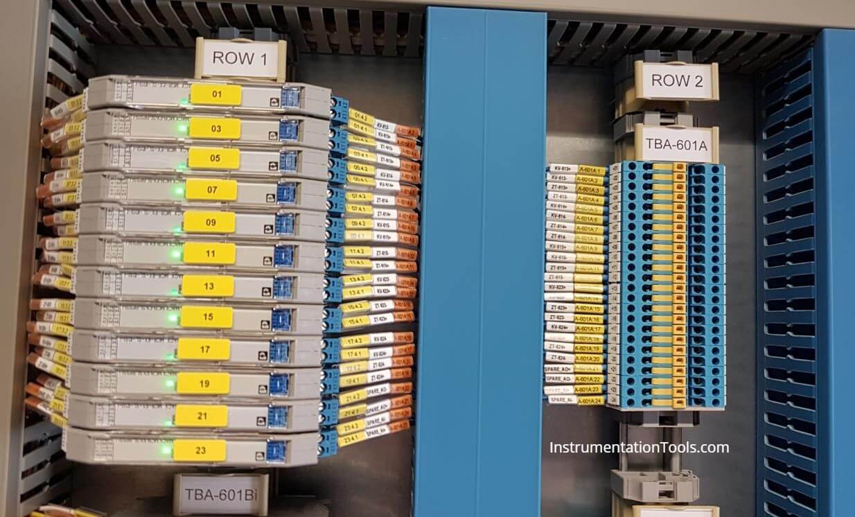
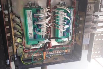
Marshalling Cabinet Photo
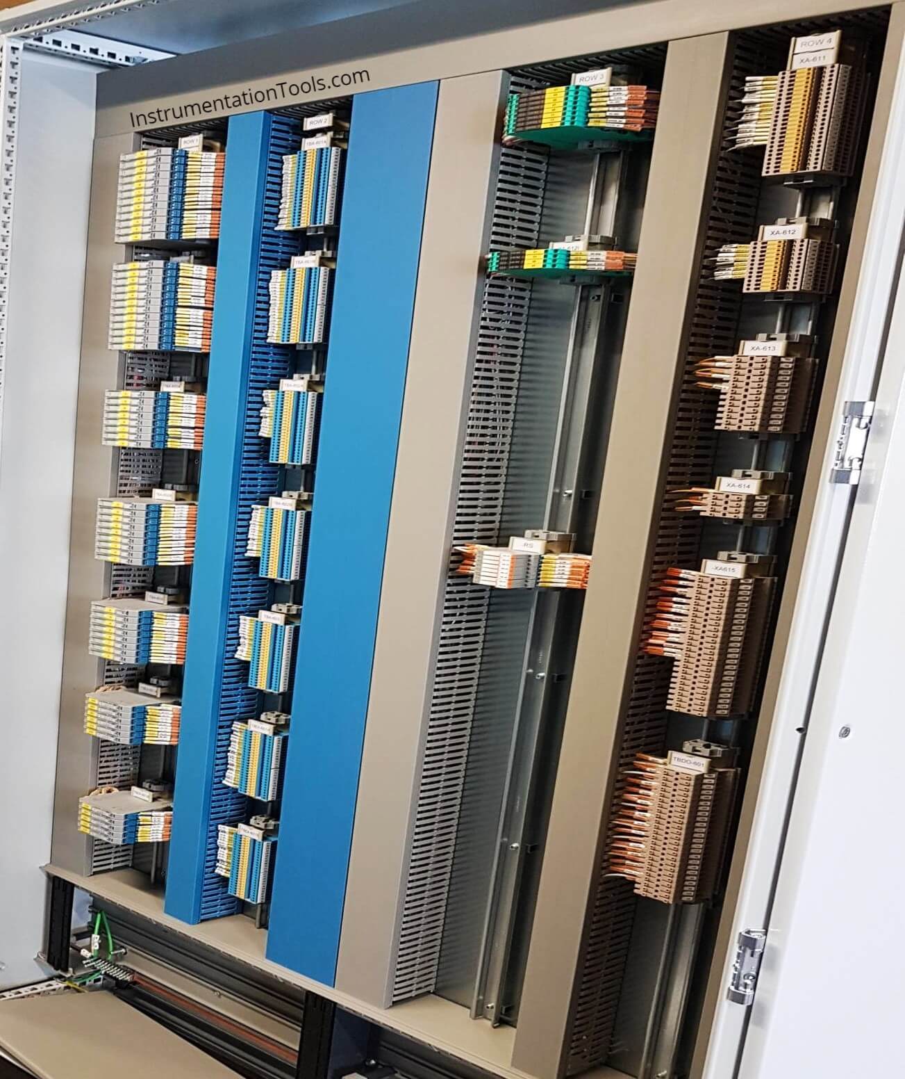
Closure view of marshalling cabinet components
Author: Jatin Katrodiya
If you liked this article, then please subscribe to our YouTube Channel for PLC and SCADA video tutorials.
You can also follow us on Facebook and Twitter to receive daily updates.
Read Next:
- Anti Surge Controller
- DCS Commissioning
- Instrumentation Earthing
- Wiring Diagrams of DCS
- Field instrument to Control Room


Great explanation. This site rocks.
Many thanks for explanation
very good
Thanks for sharing your knowledge with us, you’re amazing!
nice explanation. could you please extend the explanation by is any tools can be used for for tracking and termination arrangement, setup
VARY NICE