Inst ToolsInst ToolsInst Tools
  • Courses
  • Automation
    • PLC
    • Control System
    • Safety System
    • Communication
    • Fire & Gas System
  • Instrumentation
    • Design
    • Pressure
    • Temperature
    • Flow
    • Level
    • Vibration
    • Analyzer
    • Control Valve
    • Switch
    • Calibration
    • Erection & Commissioning
  • Interview
    • Instrumentation
    • Electrical
    • Electronics
    • Practical
  • Q&A
    • Instrumentation
    • Control System
    • Electrical
    • Electronics
    • Analog Electronics
    • Digital Electronics
    • Power Electronics
    • Microprocessor
  • Request
Search
  • Books
  • Software
  • Projects
  • Process
  • Tools
  • Basics
  • Formula
  • Power Plant
  • Root Cause Analysis
  • Electrical Basics
  • Animation
  • Standards
  • 4-20 mA Course
  • Siemens PLC Course
Reading: Foundation Fieldbus Split Range Valves
Share
Notification Show More
Font ResizerAa
Inst ToolsInst Tools
Font ResizerAa
  • Courses
  • Design
  • PLC
  • Interview
  • Control System
Search
  • Courses
  • Automation
    • PLC
    • Control System
    • Safety System
    • Communication
    • Fire & Gas System
  • Instrumentation
    • Design
    • Pressure
    • Temperature
    • Flow
    • Level
    • Vibration
    • Analyzer
    • Control Valve
    • Switch
    • Calibration
    • Erection & Commissioning
  • Interview
    • Instrumentation
    • Electrical
    • Electronics
    • Practical
  • Q&A
    • Instrumentation
    • Control System
    • Electrical
    • Electronics
    • Analog Electronics
    • Digital Electronics
    • Power Electronics
    • Microprocessor
  • Request
Follow US
All rights reserved. Reproduction in whole or in part without written permission is prohibited.
Inst Tools > Blog > Control Systems > Foundation Fieldbus Split Range Valves

Foundation Fieldbus Split Range Valves

Last updated: April 18, 2019 6:59 am
Editorial Staff
Control Systems
2 Comments
Share
2 Min Read
SHARE

In FOUNDATION Fieldbus systems (Note1), where a special software function block called “SPLT” exists to provide split-ranged sequencing to two valves.

The “SPLT” function block takes in a single control signal and outputs two signals, one output signal for each valve in a split-ranged pair.

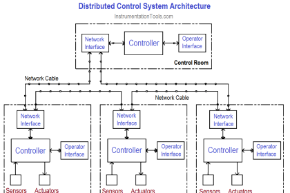
Note 1 :  To review, Fieldbus is an all-digital industrial control protocol, where instruments connect to a control system and to each other by means of a single network cable. Signals are routed not by specific wire connections, but rather by software entities called function blocks whereby the engineer or technician programs the instruments and control system what to do with those signals.

Also Read : What is Split-Range Control ?

The function blocks shown in this example would typically be accessed through the graphic display of a DCS in a real Fieldbus system, lines drawn between the blocks instructing the system where each of the instrument signals need to go.

Foundation Fieldbus Split Range Valves

The function block diagram for such a system appears here:

Split Range in Foundation Fieldbus

In this Fieldbus system, a single PID control block outputs a signal to the SPLT block, which is programmed to drive two unique positioning signals to the two valves’ AO (analog output) blocks.

It should be noted that while each AO block is unique to its own control valve, the SPLT and even PID blocks may be located in any capable device within the Fieldbus network.

With FOUNDATION Fieldbus, control system functions are not necessarily relegated to separate devices. It is possible, for example, to have a control valve equipped with a Fieldbus positioner actually perform its own PID control calculations and split-ranged sequencing by locating those function blocks in that one physical device!

Articles You May Like :

Fieldbus Coupling Devices

What is Foundation Fieldbus (FF) ?

Proportioning Feedforward action

Logic Gates in PLC Ladder Logic

Fieldbus Flow Transmitter Configuration

Don't Miss Our Updates
Be the first to get exclusive content straight to your email.
We promise not to spam you. You can unsubscribe at any time.
Invalid email address
You've successfully subscribed !

Continue Reading

Why 24 Volts DC Power Supply is used? – Industrial Automation Systems
How to Export Data from DeltaV System to Excel
Industry 4.0
Interactions With Process Control Systems Philosophy
Energize to Safe Loop philosophy
What is Override Control? – Need & Applications
Share This Article
Facebook Whatsapp Whatsapp LinkedIn Copy Link
Share
2 Comments
  • Abdulrazig Elkawafi says:
    October 28, 2019 at 11:35 am

    Dear Sir

    Currently, we used water flow meter typeSiemens SITRANS F Ultrasonic flowmeters FUS060 with HART to measure the water flow rate and water accumulated flow rate from flow lines.

    The outputs of these flow transmitters are Analogue output (active) to 4-20mA; HART and Digital output (active/passive).

    These flow meters need to be connected to the existing control room that is located 5 KM away from the location of the flow meters.

    The flow meters are installed at different locations both separately and in groups.

    Group A three flow transmitters
    Group B four flow transmitters
    Group C one flow transmitter
    Group D one flow transmitter
    Group E one flow transmitter

    In total 10 flow transmitters.

    The location of these flow meters is in the desert.

    The design base of this project is to connect the existing 10 flow meters to the control room and to have real-time monitoring of the water flow.
    We hope to Receive a technical and financial offer

    Best Regards

    Abdulrazig Elkawafi
    Communication System Engineer
    E-mail: [email protected]
    Mobile: +218914031650
    main office of the GMMRA project: Alhwary Rood Benghazi-Libya
    Phone:+218612225091-92
    Ext.2010

    Reply
    • S Bharadwaj Reddy says:
      October 29, 2019 at 10:06 am

      Hi,

      We do not do any type of sales.

      Reply

Leave a Reply Cancel reply

Your email address will not be published. Required fields are marked *

Stay Connected

128.3kFollowersLike
69.1kFollowersFollow
210kSubscribersSubscribe
38kFollowersFollow

Categories

Explore More

UPS Selection Factors for a Control System
Problem on Pressure and Level Control Loops
Basics of Process Control Systems
ICS Control System Security
Derivative (Rate) Control Theory
Difference between Fieldbus, Profibus and HART Protocols
Comparing ICS and IT Systems Security
Cascade Control

Keep Learning

Alarms to Annunciator

Basics of Alarms and Trips

Networked SCADA Architecture

Types of SCADA System Architecture

SCADA RTU TELEMETRY

SCADA & Telemetry Systems

DCS ESD Logic Overview Graphic Display

Automation System Process Functionalities

HART Transmitters Loop Checks

Loop Check of 4-20mA or HART Transmitters

PID Tuner

Free PID Controller Gains Tuning Tool

Building Management System

Building Management System

Level Control Loop Principle

Integrating Processes – Liquid Level Control

Learn More

Liquid Level Switch Control Pump and Lamp

Liquid Level Switch Control Pump and Lamp

PLC Logic for Water Pumping and Chemical Addition

Developing PLC Logic for Water Pumping and Chemical Addition

PLC Compressor Control Ladder Logic

PLC Compressor Control Ladder Logic

Belt Sway Switch Principle

Belt Sway Switch Working Principle

PLC-based mail box automation

PLC Program for Mailbox with Letter Counting & Light Indicators

Ultrasonic Level Switch Working Animation

Ultrasonic Level Switch Working Principle

9 Best E-Book Apps for Students

9 Best E-Book Apps for Students

DCS Vs PLC

Difference between DCS & PLC Systems

Menu

  • About
  • Privacy Policy
  • Copyright

Quick Links

  • Learn PLC
  • Helping Hand
  • Part Time Job

YouTube Subscribe

Follow US
All rights reserved. Reproduction in whole or in part without written permission is prohibited.
Welcome Back!

Sign in to your account

Username or Email Address
Password

Lost your password?