Yokogawa’s CENTUM VP is a leading distributed control system (DCS) that is widely used in a variety of industries for process control and monitoring. It offers an integrated production control system that combines a high degree of reliability with outstanding performance. Here’s a general overview of the CENTUM VP DCS system architecture.
Yokogawa CENTUM VP DCS System Architecture
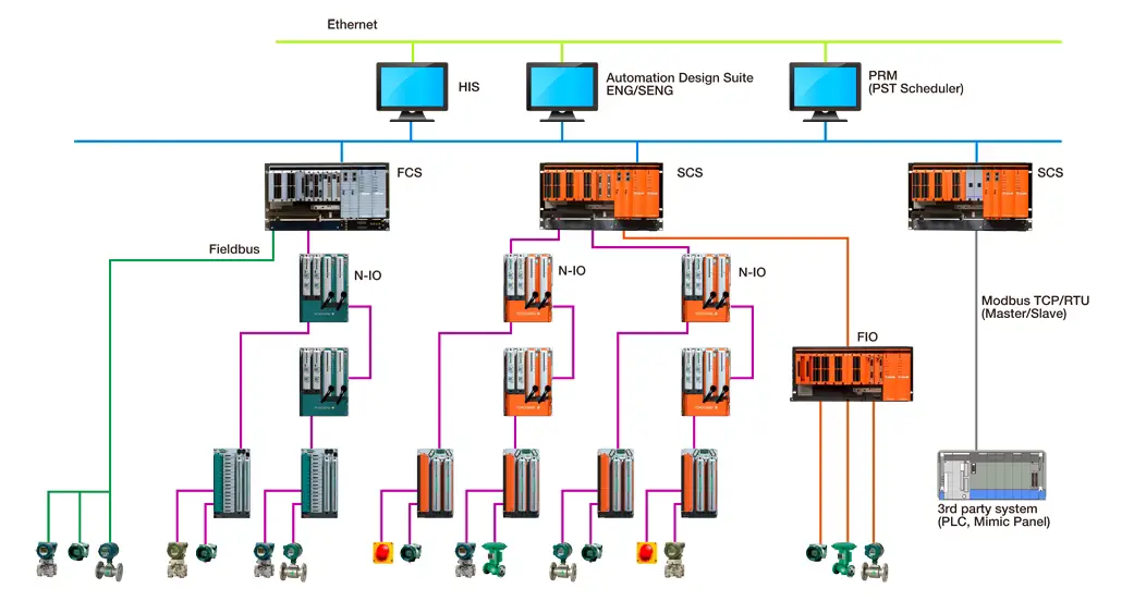
Image Courtesy: Yokogawa
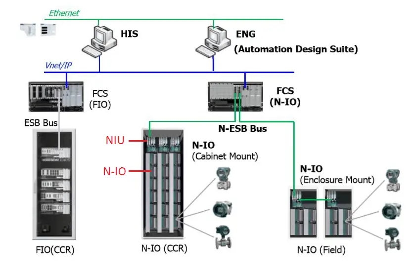
Yokogawa’s CENTUM VP R6 innovates the engineering environment of DCS. Specifically, it reduces the time and effort required for system construction and engineering. As a further enhancement, a new I/O system, Network I/O (N-IO), was added to the I/O lineup for CENTUM VP.
Earlier Yokogawa system was F-I/O (Field I/O) based. Its control network which uses very high speed Vnet/IP (One Gigabit per second) guarantees operator screen update times within 1 second. Vnet/IP is complying with IEEE 802.3.
- FCS – Field Control Station;
- NIU – Node Interface Unit;
- N-IO – Network I/O;
- FIO – Field I/O;
- HIS – Human Interface Station (Operator workstation);
- ENG – Engineering Station
Yokogawa’s Centum VP DCS is Distributed Control Architecture which is not based on Client/Server Architecture. In this architecture the database is distributed in each Field Control Station (FCS) which is entirely redundant with less than 1ms switchover time.
The Main Copy of this distributed database resides in the Master Engineering Station. However, this is only a copy with the main database distributed & residing in the Controller. This architecture offers unique advantages which client server architecture cannot offer.
These are
- Operator Stations directly fetch data from Controllers (and not through Server). Hence Yokogawa System display update times is 1 sec.
- The architecture is not based on Servers & hence there is no possibility of loss of data during server switch-over.
- No Single point failure (In case of Client Server architecture, loss of servers’ results in loss of data to all the operator stations).
- Individual units can be independently commissioned and later the database can be merged on the Master Engineering Station.
- Each operator station can act as Historization Node.
- Failure of one Operator Station or even the Master Engineering Station does not affect the system performance or operability of the plant.
FCS performs control computation functions for each function block and input/output functions for process and software inputs/outputs
HIS is the HMI of the CENUTM VP system for operation and monitoring of plant.
ENG is a computer used for CENUTM VP system configuration and maintenance
Vnet/IP is a control network for connecting CENTUM VP components with each other
N-IO (Network I/O) is the next-generation Smart Configurable I/O.
For Intrinsically Safe type N-IO design
Yokogawa corroborates with MTL and Pepperl+Fuchs for Intrinsically Safe I/O in hazardous areas. Universal I/O module and their Isolated Barrier (of MTL’s/ Pepperl+Fuchs) install on N-IO baseplate.
Vnet I/P network provides real-time communication with high reliability which is indispensable for stable plant operations. Vnet/IP is a dual-redundant control network, consisting of Bus 1 and Bus 2. Bus 1 is normally used for control communication to transmit control data; however, when the Bus 1 fails, it automatically switches its communication path and Bus 2 continues the control communication without stopping. Furthermore, Bus 2 is capable of handling open communication, the generic Ethernet communication with Non-Centum component like printers. Failure of bus-1 or bus-2 shall in no way limit the open communication.
The Vnet/IP uses general-purpose communication devices for network connection. All the Vnet I/P components like FCS and HIS in a domain are connected to the 1Gbps Ethernet Layer-2 switch. Multiple domains are connected via Ethernet Layer 3 switch. The Vnet/IP domains can be in hierarchy configuration
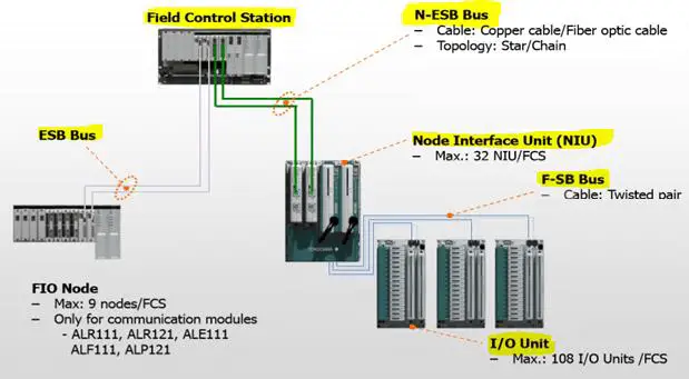
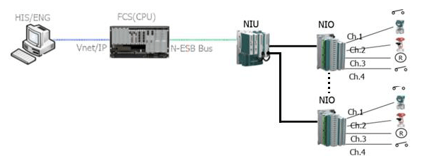
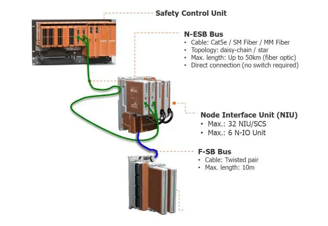
As shown in earlier figure that, NIU Networked interface units are connected to Controllers via N-ESB cables and bus coupler modules. One NIU can handle 6 nos of Networked I/O modules (N-I/O). One N-I/O can cater 16 no of configurable channels.
One FCS can handle 32 NIUs and 108 N-I/Os (1728 I/O Channels); Each NIU can handle = 6*16 = 96 I/Os
Redundant I/O modules are A2MMM843 which is HART pass through meaning that we do not need extra HART multiplexer. With A2MMM843 I/O module, I/Os can be configured to 2 wire AI, 4 Wire AI, DI, DO with wetted output and DO with contact output. For that below I/O adaptors can be used along with A2MMM843.
All I/O modules i.e. A2MMM843 are connected to NIU individually (No multi dropping). All NIUs are connected to Bus coupler module via ESB Bus / N-ESB Bus / Optical ESB cables. Bus coupler modules installed on controller unit (node) generally talk to CPU/controller. ESB Bus / N-ESB Bus / Optical ESB are decided based on Local NIUs and Remote NIUs.
DCS I/O Adaptors for configurable I/O Types
Left side of N-I/O can be used for field cabling, meaning that Field signals wires are directly connected to I/O modules without any terminal’s blocks. This will have reduced cabinets, reduced inter panel wiring and overall reduced footprints.
The Model number for reference purpose, shown in below table.
Networked I/O System
Networked I/O System should be designed carefully keeping following points in mind,
- Field cables are directly connected to I/O cards, hence number of cables going to one cabinet should be limited. e.g. Front side of 800 W x 800 D x 2000 H cabinet can accommodate 15 I/O modules (N-I/Os) and 3 Nos of NIUs, same is the case for rear side of same cabinet.
- Junction box grouping should be perfect so that cable can be terminated directly to I/O card same as junction box image (Sequence). Change in junction box grouping will have adverse impact on I/O assignment.
- Some field cables will have both Redundant and non-redundant signals, it may not be possible to segregate redundant and non-redundant signal in one N-IO card of 16 channels. Yokogawa may need to use redundant I/O modules for such cases, since DCS side termination is mirror image of Junction box.
- As far as possible, parallel equipment’s related I/Os should be separated in different cables for more availability so that they can be assigned in different I/O cards / NIUs. If those signals are assigned in one cable that will be terminated in one I/O card, if that I/O card fails then those equipment’s are not available for control.
- Spare philosophy of Channels should be agreed with client and DCS vendor. e.g if 5 Pair field cable has 3 signals and 2 spares and then 3 Signals are directly connected to I/O card. Remaining 1 signal can be considered as wired spare to I/O card, also 1 pair is left without any termination behind the I/O module. Philosophy shall be agreed with client at earlier stage of design, once I/O assignment is frozen as described above then it would be very difficult to adopt new philosophy.
To take advantages of configurable I/Os and keep marshalling cabinet similar to old fashioned, there is an option that we can have field wire termination at separate Terminal board (A2BM4) in Marshalling cabinets and then prefab cable is connected to I/O module (A2MMM843) which is in system cabinets. This design will have increased footprints yet offers maintenance flexibility.
Yokogawa Prosafe RS System (SIS)
Yokogawa ProSafe RS R4 is IEC/TÜV certified to meet the SIL 3 classification requirements. ProSafe RS is a fail-safe, standalone system that does not rely on any other systems to fulfil its function.
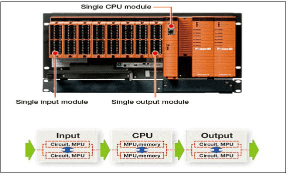
Figure: Prosafe RS Single CPU SIS System
ProSafe-RS system features physical redundant CPU with dual CPUs and Dual Circuits in-built in each card, physical redundant I/O module with dual CPUs and Dual Circuits in-built in each card, redundant power supply and redundant communication hence ProSafe-RS is SIL3 certified by TÜV even in single configuration.
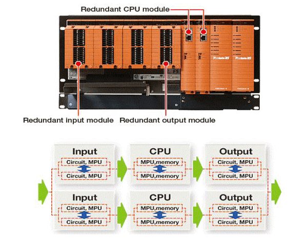
Figure: Prosafe RS Redundant CPU SIS System
ProSafe RS is normally integrated with the Centum VP DCS on the same Vnet/IP control network. The adoption of ProSafe RS eliminates the need for a separate gateway between DCS in terms of CENTUM VP and Safety Instrumented System.
A common Human machine interface serves both the DCS & ESD/F&G functions, Operators can access to safety data by using the same HMI used by CENTUM VP. ProSafe RS happens to be true implementation of “One process, One Network, One Window, One solution” concept.
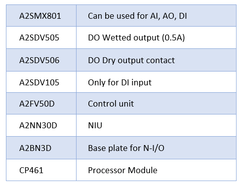
SIS configurable I/O Types
Yokogawa SIS I/O card do not require any adaptors (that is required in case of DCS)
The Model number for reference purpose, shown in below table.
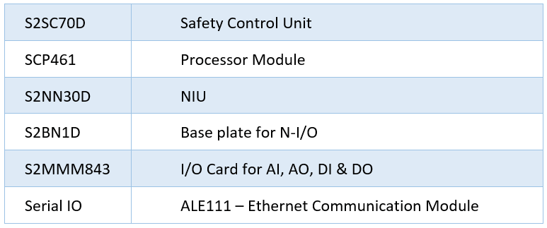
Default output of DO type signal is Wet type (24V DC, 0.2 A per channel). In case of Dry output external relays can be used. However, relay installation location should be critically reviewed in order to avoid interpanel / intrapanel wiring. Functionality of N-IO based Prosafe RS is similar to Centum VP DCS.
Project Execution
Typical Meetings /workshop during project execution
Following is typically applicable for any project execution with any control system vendor, this list is for example only.
- Kick off meeting
- System Architecture and network philosophy
- Typical Panel drawing review
- Automation concept
- Hardware Freeze
- Software Freeze
- Hazop / SIL study
- Alarm Rationalization
- Interface with package vendors (Serial communication, logic, graphics, C&E etc)
- FAT Readiness meeting
- Final closure and handover
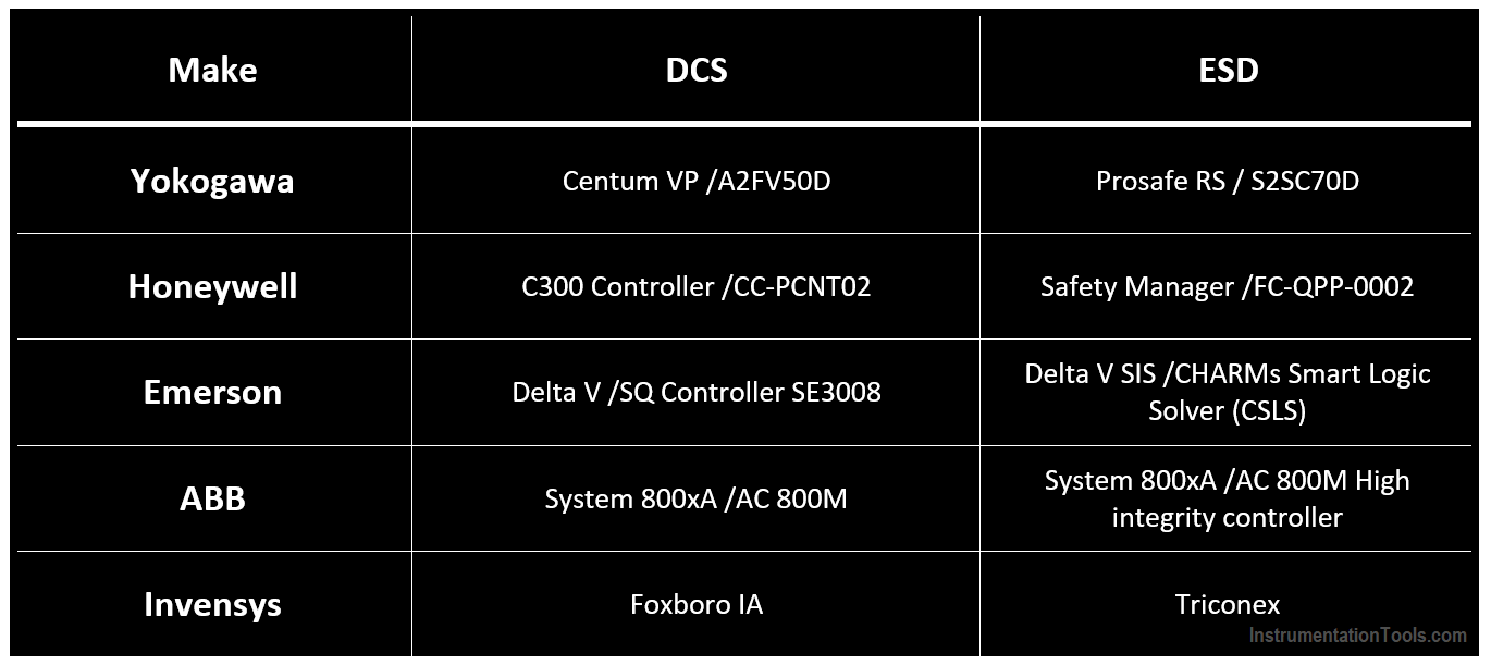
DCS and ESD Make and Models
Following is example of DCS and ESD controller Make and models.
Typical Control System Engineering Input, output and requirement matrix:
Input Documents to Control System vendor
- Control System Specifications Advanced solution specifications (Alarm management, Operator Training System, Asset performance monitoring system, Plant information management system, Cyber security, Production management, Advanced plant control, Reporting tools etc).
- Basic System Architecture.
- I/O List + Cable Grouping, (Including Alarm and trip list), MCC I/O List and cable grouping at Control system side and MCC side.
- Functional Schematics.
- P&ID / F&G Layouts / Electrical Layouts / CCTV layouts or Mapping with F&G detectors.
- Logic Diagrams / Control Narrative / Control philosophy / Cause & Effect diagram.
- HAZOP & SIL Study Reports.
- Control Groups.
- Trend Groups.
- Serial Interface Database and number of 3rd party system interfaces, type of media (FO/Ethernet/RS485) and protocol (OPC, TCP/IP, RTU etc).
- Hardwired Auxillary Console requirements (Push buttons, selector switches, Lockable PB, annunciation, LEDs, buzzer etc).
- Control Room Layout.
- Power Distribution by DCS Vendor’s Distribution panel (3rd party loads other than DCS/ESD Load).
Minimum details required by Control System Vendor for complete solution
- Spare requirement in hardware, software, licenses etc
- Integrated network or Separate control network for DCS and SIS
- Number of domains of system (single / Multi domain) and topology
- Scan time requirement for DCS and SIS (Close loop, open loop, display, command, etc)
- I/O Card, controller, communication redundancy and Segregation philosophy
- IS or N-IS Protection method In case of IS : Barrier / Isolators
- Time synchronization philosophy
- SOE requirement and stamping detail
- Watch dog logic for continuous monitoring of subsystem
- Dead band setting for Alarms
- HART multiplexer requirement for subsystems and Number of HART I/O for Asset management system sizing and design, Valve signature software etc
- Faceplate naming convection (due to limited character for Tag no and description)
- Process override and maintenance override requirements
- Redundant servers vs simplex servers
- Smoke detectors / HSSD requirement inside indoor/outdoor panels
- Reliability and availability requirement
- IP Addressing of Subsystems
- Wiring and color code specification
- Distance b/n DCS cabinets/sub systems in case of remote I/O concept, FO Core allocation and topology (e.g. Ring), FO link power budget
- Painting and shed/canopy design for outdoor cabinets
- HVAC requirements, Clean agent system interfaces
- UPS input voltage, frequency and Floating or earthed neutral
- Scope split between other vendor for interface and selection of hardware/software
- Workshop / special study requirement
- Training requirement
- Vendor documentation requirement
Output Documents by Control System vendor
- Compliance statements, Functional design Hardware, Functional design Software, Detailed System Architecture, Interconnection Diagram, Typical panel design Software package GAD of System/ Marshalling/ Network/ Server / Remote I/Os Cabinets Method Statements FAT procedures.
- I/O Assignment, Point configuration, Controller Loading, Scan time calculations, Power consumption calculations, Interposing relay Cabinets design.
- Graphics Design, Faceplate requirements, Typical Drive / Valves blocks, Detailed sequential / control scheme.
- Logic interlock Diagrams, Functional scheme for complex calculation / selection First out logic.
- SIL Validation plan for SIS.
- Graphics design level 1,2,3,4.
- Trend, groups configuration.
- Communication modules, Firewalls, network switches, licenses, configuration details etc requirement.
- Detailed layout of workstations, Telecom, CCTV, PAGA, Tetra, Electrical systems, Packaged system workstation etc & furniture.
- Adequacy check of room size and preference of cabinet placement requirement, prefab cable length etc, Earthing philosophy.
- Total UPS / Non-UPS load requirement, Power Distribution scheme with MCB, Isolator ratings, feeders’, and heat load details.
- PDP Panel Upstream Feeder rating and power cable selection.
Note: This list can be updated based on project actual scope and requirement by end user.
The information is provided for general informational and educational purposes only. All views expressed on this information are my own and do not represent the opinions of any entity whatsover with which I have been, am now, or will be affiliated. I encourage you to consult your control system vendor for latest information and technological changes.
Author: Jatin Katrodiya
If you liked this article, then please subscribe to our YouTube Channel for PLC and SCADA video tutorials.
You can also follow us on Facebook and Twitter to receive daily updates.
Read Next:
- Earthing in DCS System
- Wiring Diagram of DCS
- DCS System Layout
- Compare DCS, PLC, and RTU
- Field instrument to Control Room


plz I have more knowledge in yokogawa dcs
Hi, first of all, this is a very nice article! It shows a lot of relevant information to be used for system architecture.
However it would be nice if OT Cybersecurity is mentioned. The location of the firewalls (could be both software or hardware) is essential to a safe and secure architecture.
The subject is too large to be descriptive here and hence mentioning it would be a great step in the right direction.
Good luck and please continue producing articles like this!
Ted Angevaare, TAPS
http://Www.TedAngevaare.nl
TAPS@TedAngevaare.nl
excellent
Hi
It is so excellent
And the codes to design of control system and Instrumentation is needed
How about Honeywell EPKS R522, virtuall version
Do you have docs?
Yoko is a flat architecture. The advantage is there is not server hence centralized failure is avoided. But lets talk about huge projects were lots of third party data like modbus TCP/IP, OPC data to be taken from DCS to other systems. This is were server client with inbuilt gateway.
For a DCS it should support both flat & server architecture and the customer should be able to select it. Also NIO technology is something DeltaV launched in 2010 and Yoko/ABB brought in. This is not Disruptive. See how Honeywell has matured the IO Hive & Control HIVE. They are disruptive like Emerson CHARMS. Makes sense to see as new gen and not a copy cat.
Will each operator station fetch data directly from the controller? Won’t it impact the controller loading?