In Boiler, the Draft Plays an Important role. If the Draft of the Boiler Furnace is not Control Properly there are the Chances of Back firing and also the heat can be realised from chimney without its proper use gage these will reduce a boiler efficiency.
DCS Program to Maintain Draft in Furnace

Problem Solution
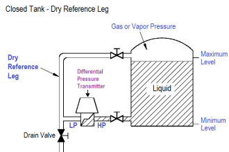
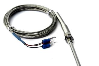
- First for controlling the Draft we will Required to Measure the Draft in the furnace these can be done by using a Differential Pressure Transmitter (DPT).
- We will use Honeywell series STD700 DPT whose range is (0-10000 mmwc). Which work on 24VDC and Output will be standard 4-20 mA, in proportional to LRV, URV, and PV.
Example:
Consider the DP transmitter LRV and URV as follows.
LRV= +50
URV=-50
Then the Transmitter will Scale itself for 4-20 mA such that if we will receive 4 mA it will show +50 process Value and 20 mA shows -50 process value.
- The Scale on SCADA will be same as set in DPT transmitter LRV +50 and URV -50
- The Command from the DCS will be send to VFD which is used for ID fan, which will control the Draft in Furnace.
- The Command from DCS will be in form of 4-20 mA Analog Output which will be Input for VFD.
Details Explanation:
Analog Out from DCS, ID Fan Speed: 0 – 980 RPM (4 – 20 mA)
Analog Input to DCS, Speed Feedback of VFD: 0 – 980 RPM (4 – 20 mA)
So let’s start for the implementation of Program in DCS using function block diagram (FBD).
DCS Program
This DCS program is to Maintain Draft of the Boiler Furnace, along with program explanation and run time test cases.
List of Inputs and Outputs
ADDRESS Description Signal Type
00(02-06) ID Fan Start/Stop Command DO
07(02-00) ID Fan RPM Command AO
00(02-00) ID Fan RPM Feedback AI
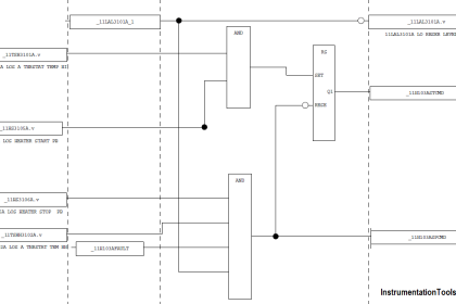
Program in FBD language

Fig. No. (a) Input assigning

Fig. (b) Output Assigning

Fig No. 1.0 PID Block with Library

Fig No. 1.1 PID Blocks in DCS Software
DCS Program Description
- Here we are using a Functional Block Diagram for Programming in DCS System.
- The ID Fan will start when We are Latching The DO located on address 00(02-06)
- If we give a Stop command from SCADA to VFD then it will De-latch the Signal and the ID fan will Stop.
- The Figure1.1 Shows the PID Block used for the draft control the input to PID block is Signal from DPT.
- And the Output of the PID block is given to VFD in form of 4-20 mA to VFD (AO).
- The PID block will try to Mention the Set point set by the operator (-2mmwc).
- Here we will inverse the action of PID controller means if the set point is met the ID fan will Low down its RPM. Or if the draft is in positive then the ID fan RPM will be increase to met the set point.
- The Figure 1.2 shows the graph of how the ID fan is trying to control the Draft within given span range.
- The running feedback taken from ID fan will show us on which RPM the ID fan is Rotating without need of any field survey.
- For your best knowledge the draft of furnace is always kept -2mmwc.
- The below table will give you a summary of working of ID fan.

Author: Amit Jadhav
Read Next:
- What is DCS ?
- DCS System Layout
- Compare DCS & PLC
- Control System Security
- System Architecture
- Industrial Control System
- Purpose of ESD System


what is the simulation software used?
nice article