Specification of DCS and ESD based control systems for projects of manufacturing industries shall include Design, Engineering, Manufacturing, Software Development, Supply of DCS & ESD systems with SCADA, Erection, Supervision, Commissioning, etc.
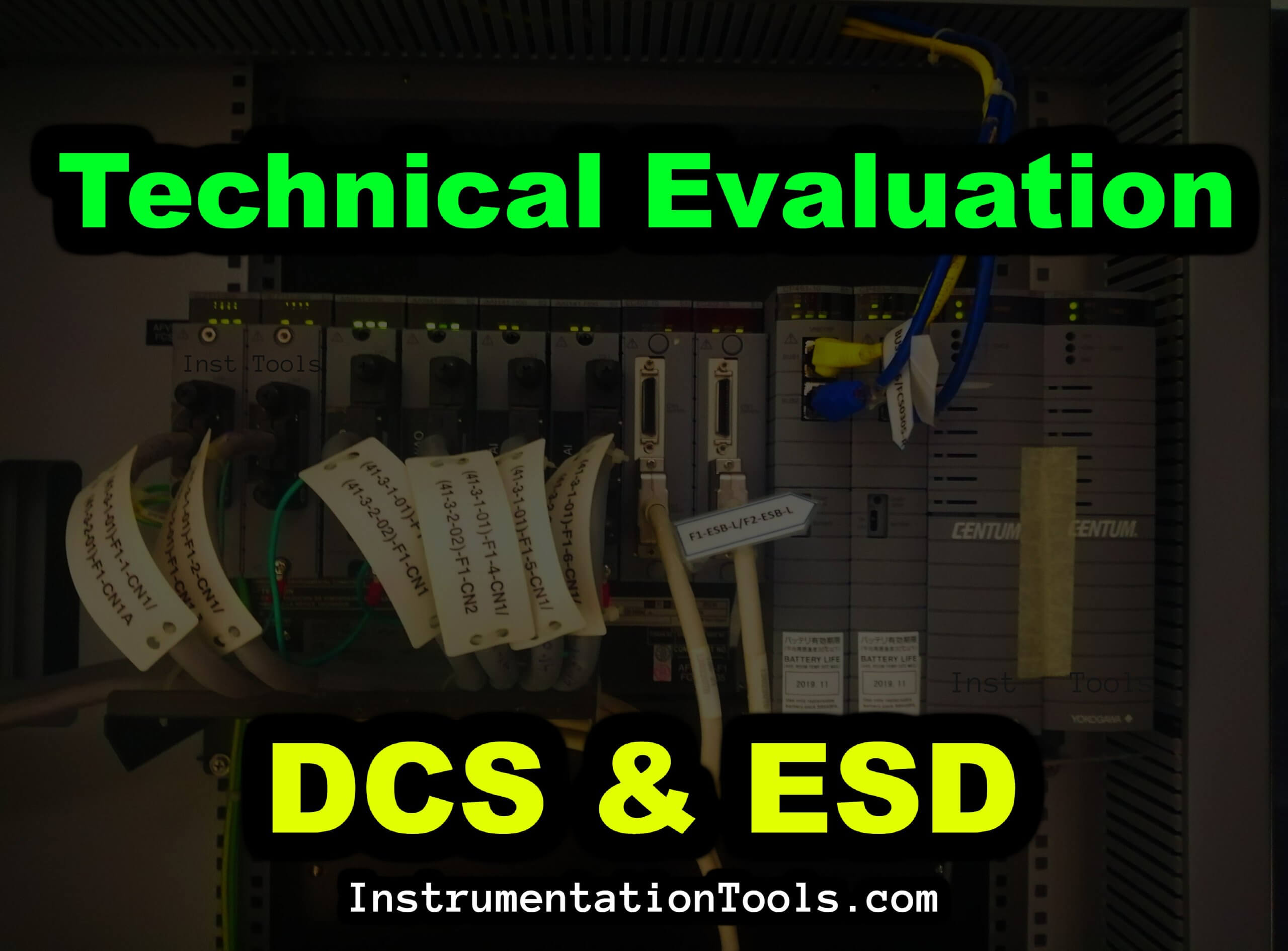
Technical Evaluation for DCS and ESD
This article covers the scope of work for the DCS and ESD systems and their general technical evaluation, specifications, and requirements.
Specification of DCS Controller
Control System vendor shall provide system solution as a standard DCS/ESD. A hybrid type solution is not acceptable. Separate hardware and software shall be considered for DCS and ESD.
DCS architecture should be Node Based and not server based. ESD system shall be independent and shall be minimum SIL-3 rated.
DCS and ESD systems shall be redundant.
The systems shall have redundancy at the following levels.
- Controller redundancy
- Power supply redundancy
- Communication redundancy
- Redundancy is optional at the I/O level for DCS systems and
- I/O’s shall be redundant for the ESD System
Transfer of control shall be achieved in an order of 100ms. The failed module when replaced shall update the program from the running processor. It shall be possible to make the hot-standby processor learn from the active processor and update itself to function as a hot-standby.
The standby processor shall continuously equalize with the primary processor. There shall be Bump less Transfer of control between Active Processor and Standby Processor.
The processor should be 64 Mbytes memory. The DCS and ESD system should be suitable to operate continuously in a given atmospheric condition. Hence the system hardware shall be considered with anti-corrosive G3 Coating as per Standard ANSI/ISA S71.04-1985.
DCS and ESD shall have extensive self-diagnostic capabilities and the capacity to identify any faulty channels in input/output cards, faulty system cards, power supplies, etc. ESD System I/O cards shall be hot swappable.
Since the ESD system is intended to be used for Plant safety applications, the following failure effect of the ESD system shall be evaluated and addressed in the design.
- Interruption, excursion, dips, recoveries, transients, and partial losses of power
- Memory corruption and losses.
- Information transfer corruption and losses.
- Inputs & Outputs (Fail-on, Fail-off)
- Processor and I/O Faults
Operator stations shall be industrial grade and designed such that no plant data/system configuration will be lost in the event of any component failure to the maximum extent possible.
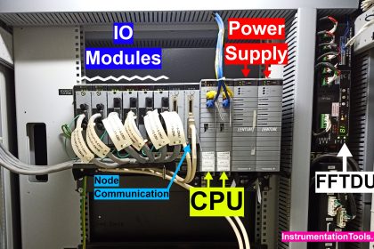
The vendor/client should select DCS and ESD hardware modules after understanding the total process requirement.
Specification of I/O Cards
In I/O modules, the following configuration shall be generally followed:
- AI/AO modules shall be less than or equal to 16 channels
- DI/DO modules shall have less than or equal to 64 Channel & Termination board shall be 32 channels.
- All cards shall have card healthiness status on them.
- The scan time of DCS shall be of the order of 100ms inclusive of processor time required for diagnostics and peripheral data transfer.
- The scan time of ESD shall be of the order of 100ms for TMR and 250ms for QMR inclusive of processor time required for diagnostics and peripheral data transfer.
- Earthing for DCS and ESD in the plant is as below
- Isolated system earth
- Isolated Cable screen earth
- Isolated Panel cabinet body earth
- The processor shall have the capability to implement all the control functions required as per the logic scheme indicates. Vendor to mention tentative CPU loading in technical offer. Maximum loading of the processor shall not exceed 60%. Detail calculations for CPU loading shall be provided during detail engineering. The size of memory shall be sufficient for the storage of program instructions required by the logic scheme.
- The healthiness of the processor shall be continuously monitored by a watchdog timer. Any hardware or software problem in the processor subsystem including CPU, memory, power supply, communication interface, etc. shall cause the watchdog timer to report processor failure.
- The memory shall be non-volatile. However, in case volatile memory is provided, battery backup shall be provided with a minimum of a month’s lifetime to keep the program storage intact. Battery low information should be available in advance at least one week before the battery gets drained.
- Ethernet Switches for Network cable connection and LAN connection with other elements of the system in the System cabinet. Ethernet switches shall be managed type. Ethernet switches shall have a minimum of 2 Nos of FO Ports.
Specification of Panel & Console
Standalone control panels/cabinets (Rittal/Eldon/Hoffman make), and bottom cable entry should be considered.
Panels shall have doors on the Front and Rear Side with Double Front & Double Rear Doors.
The control panel shall have ingress protection IP 52 as a minimum. Preferred Panel size [HxWxD]mm: [2100mm(2000mm+100mmplinth)] X [1200mm(600mm+600mm) Doors] X [800mm].
Paint shade for interior and exterior RAL7035 and Paint shade for base frame/Channel Base shall be RAL7022.
In the control panel/cabinets, there shall be 30% of spare space for future local expansion if any.
The marshalling cabinets shall be separate for Analog I/O’s and separate for DI’s & DO’s. Interposing relays shall be provided for all the digital outputs.
The system cabinet consists of all types of electronic modules including CPU, I/O modules, etc. The node Interface units (NIU’s) should be on the front side of the system cabinet. Power and signal wiring shall be separated.
Specification & Requirement of the DCS & ESD Software
The system shall include the required software for DCS/ESD and the programming terminal. Programming software shall be preloaded on the Engineering station and a CD shall be delivered along with the system.
- Programming language: Ladder logic and functional block shall be provided for the DCS and ESD programming.
- It shall be possible to modify the application program online and upload it to DCS/ESD without affecting plant operation. The system should have the capability of logging the engineering changes made along with the detailed activities, user name, and time stamp.
- Necessary Hardware & Software requirements
- OPC
- HART PASS system
- Hot Swappable Cards
- AMS (Asset Management system)
- SOE (will be defined at a later stage)
- Web server
- GPS Clock
- 20% Spare IO to be considered with installed modules and wired terminals.
If you liked this article, then please subscribe to our YouTube Channel for Instrumentation, Electrical, PLC, and SCADA video tutorials.
You can also follow us on Facebook and Twitter to receive daily updates.
Read Next:
- 4 to 20 mA Formula
- BPCS Control System
- DCS System Safety Barrier
- Marshalling Cabinet Tests
- Commissioning of DCS System


HONEY WELL DCS AND ESD TRAINING