Process Control
In almost all industrial process applications, control of process variables is critical to the safe and efficient operation of the process. The most common variables controlled are pressure, level, temperature, and flow.
Even though there are many different methods used to control these processes, this monitoring and control is generically called process control. Level, pressure, temperature, and flow are all controlled in a similar fashion. In this series of modules, level control will be used to explain the various concepts and control methods.
Control Types
The type of control needed to maintain a process is dependent upon the type of process involved. Each process has its own unique set of characteristics, depending on the kind of process and the physical components that make it up.
There are two broad categories of processes: self-regulated processes and non self-regulated processes.
Self-Regulating Process
Self-regulating processes are processes that are inherently self-regulating. Self-regulated processes have built-in feedback characteristics that cause the process to tend towards self-regulation.
An example of a self-regulating process is a tank of water with an input of water entering the tank and an output of water leaving the tank. Let’s say the water level in the tank is constant at 10 inches.
Water enters the tank at a rate of 20 gallons per minute and leaves the tank at a rate of 20 gallons per minute. As long as this balance is maintained, water level in the tank will remain constant at 10 inches.
What happens if the outlet valve is opened an 1/8 of a turn and water leaving the tank changes to a rate of 25 gallons per minute?
Since this is a self-regulating process, the level will actually stabilize at a new position and maintain that position. Flow out of the tank is proportional to the square root of the differential pressure across the output valve.
As level decreases, the differential pressure will also decrease, causing the rate of drainage to decrease. At some point, the drainage rate will once again equal the fill rate, and the tank will reach a new equilibrium point.
Time Constants
Every self-regulated process has a time constant associated with it. The time constant is the amount of time it takes the process to change 63.2% of the final value of the process. In this example, the process changes by 10%.
The time it takes to change 6.32 inches (63.2% of 10 inches), is the time constant. It takes five time constants in order for the process to complete the total change.
Process Gain
The time constant is affected by the capacity of the process and the process’ resistance to change.
The larger the process capacity, the longer the time constant, and the more resistive elements in the process (small pipes, penetrations, valves, etc), the longer the time constant.
Dead Time
Dead time, by definition, is “the time difference between when a change occurs in a process and when the change is detected.”
Dead time exists in all processes and is a factor in the control loop control, which must be addressed when turning the loop.
Non Self-Regulating Process
A non self-regulating process is one where the process does not tend towards self-regulation. These processes have no self-regulating feedback characteristics and will tend towards being unstable if not controlled externally.
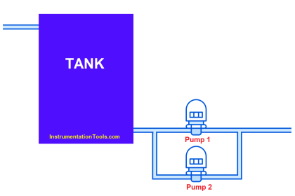
Take, for example, the initial scenario. The water level in the tank is constant at 10 inches. Water enters and leaves the tank at a rate of 20 gallons per minute. In this process, instead of having a discharge valve on the tank, a positive displacement pump is used to drain the water. As long as the balance is maintained, water level in the tank will remain constant at 10 inches.
If we increase the discharge rate of the positive displacement pump to 25 gallons per minute, what will happen? Initially, as with the self-regulating process shown before, we are removing 5 more gallons per minute from the tank than we are putting in the tank. This causes the level to drop. However, unlike the self-regulated process, this drop in level does not affect the flow out of the tank.
A positive displacement pump will discharge a set flow rate regardless of head pressure. The pump will continue to discharge at a rate of 25 gallons per minute until the tank is completely empty.
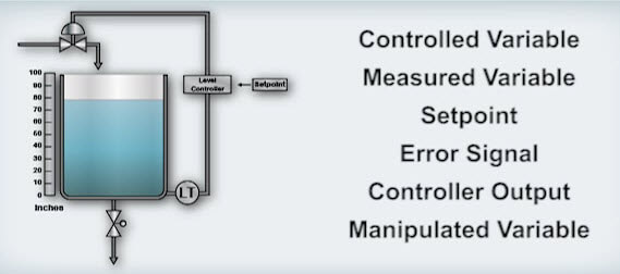
Process Control Terminology
The various components that make up a control system are seen in the diagram here. Each of these components has its own characteristics, and changing any single component will change the overall response of the control loop.
A simple control loop, shown above, is comprised of six major parts:
Controlled Variable
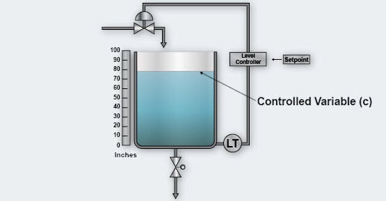
Controlled Variable – The controlled variable is a process parameter being controlled. In the example here, water level in the tank is the controlled variable, but it can be any process you wish to control.
Controlling this variable is the primary function of process control. Controlled variable is indicated with the letter “c.”
Measured Variable
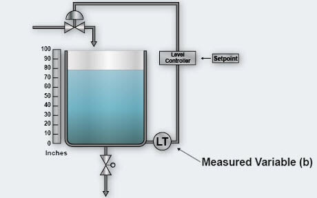
Measured Variable – The measured variable is the electronic or pneumatic representation of the value of the controlled variable.
The measured variable typically comes from a transmitter, which measures the controlled variable and produces an output representative of it.
In the example here, the level transmitter is measuring level in the tank (the controlled variable) and converting that level to a 4-20 milliamp signal. Measured variable is indicated with the letter “b.”
Setpoint
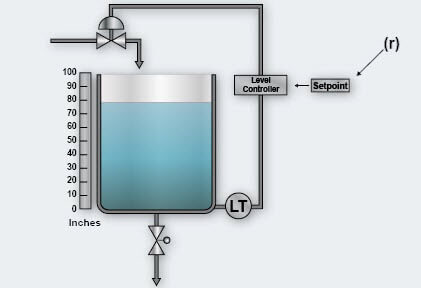
Setpoint – The measured variable is sent to the controller in the loop, where it is compared to a desired value called the setpoint. The setpoint and the measured variable are compared in order to produce an error signal.
The setpoint is often manually entered by an operator, but it can also be automatically obtained from other systems. Setpoint is indicated with the letter “r.”
Error Signal
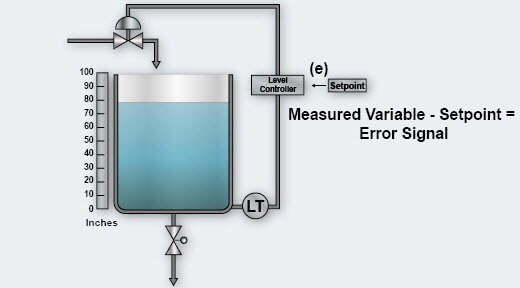
Error Signal – The error signal is the difference between the measured level and the setpoint. It can be either a negative or positive value. The error signal is then added to the base signal level of the controller to create the controller output.
For example, the base, or initial output, value of the controller may be 50% with a zero error signal. Any error signal developed by the controller is then added or subtracted to this 50% base level. Error signal is indicated with the letter “e.”
Controller Output
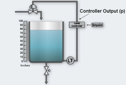
Controller Output – The controller output is simply the total output of the controller. With the controller in automatic, the output is calculated by the controller itself.
If the controller is placed in manual, the output can be manually adjusted to any desired position. Controller output is indicated with the letter “p.”
Manipulated Variable
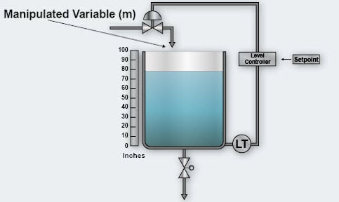
Manipulated Variable – The manipulated variable is the parameter that is adjusted to bring the process back to the desired setpoint.
The manipulated variable in this case is the water entering the tank. The water flow is manipulated in order to keep the level constant as the output demand changes. Manipulated variable is indicated with the letter “m.”
Also Read: Understanding a Process Control Loop


I wanted book concerning plc based water level control