In this article, we discussed the steps to be followed during the health checks of the PLC and DCS system cabinet.
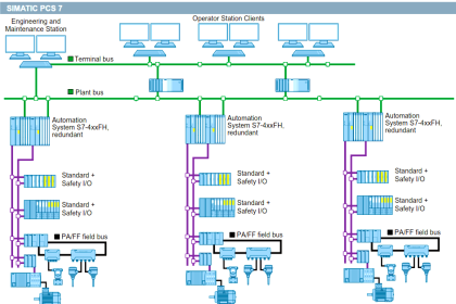
Here DCS stands for Distributed Control System. and PLC stands for Programmable Logic Controllers.
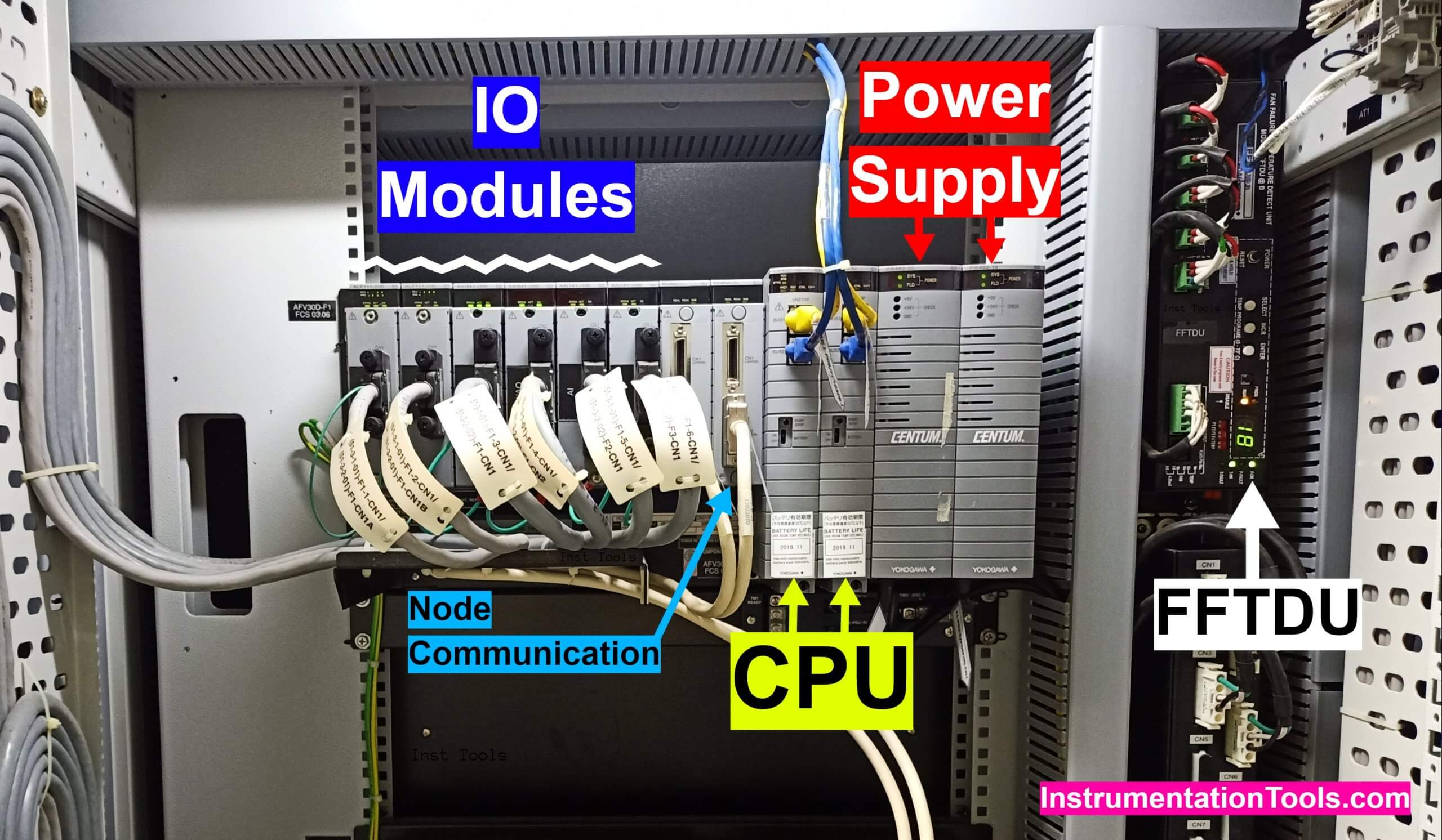
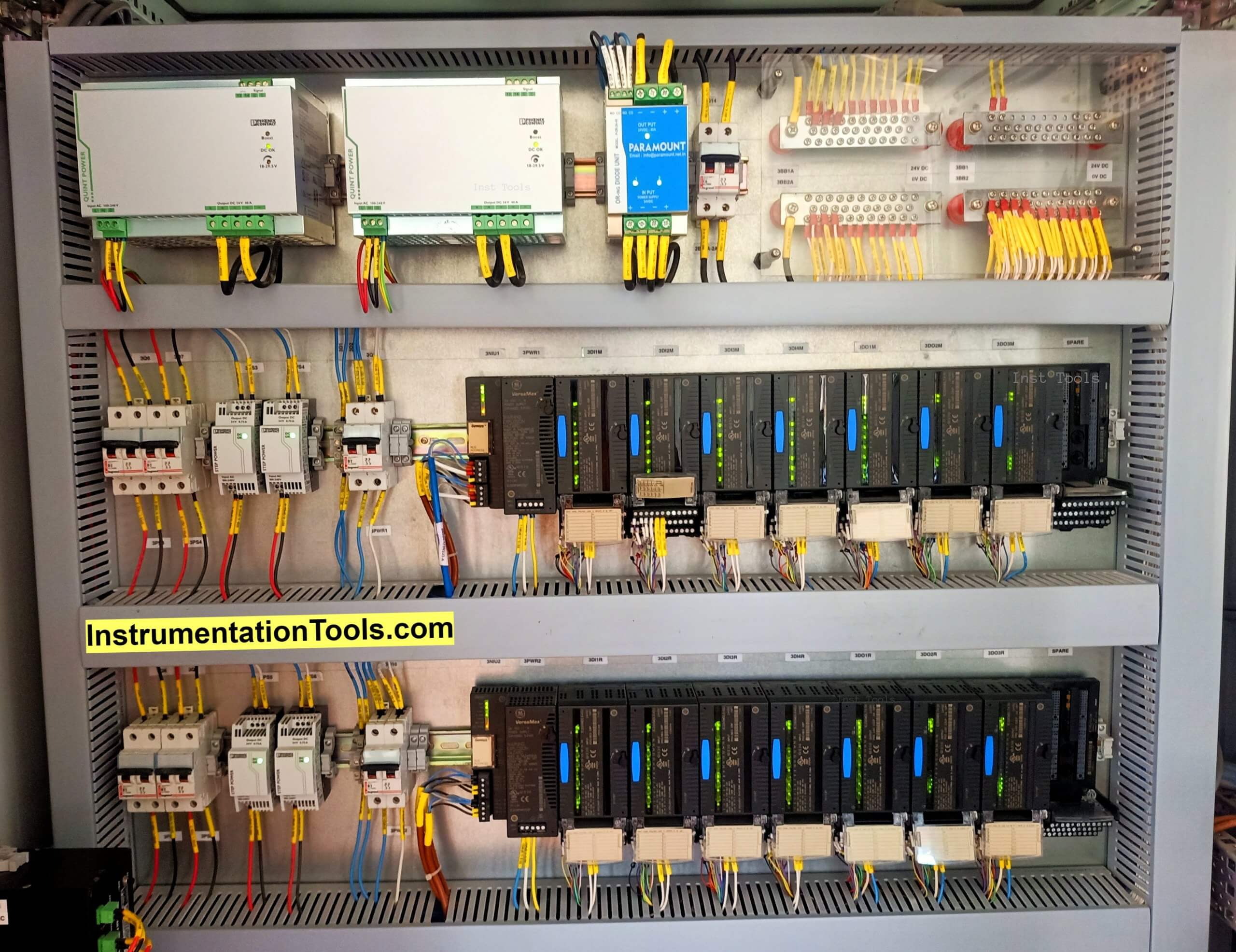
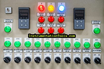
System Cabinet
Step 1:
Collect the corresponding Work permit.
Step 2:
Note down the system cabinet panel tag/reference name which will be available on top of each cabinet door (Example: 10-3-01).
Step 3:
Check the working condition of the door locking system by operating twice.
Step 4:
Check the LED status in the CPU card.
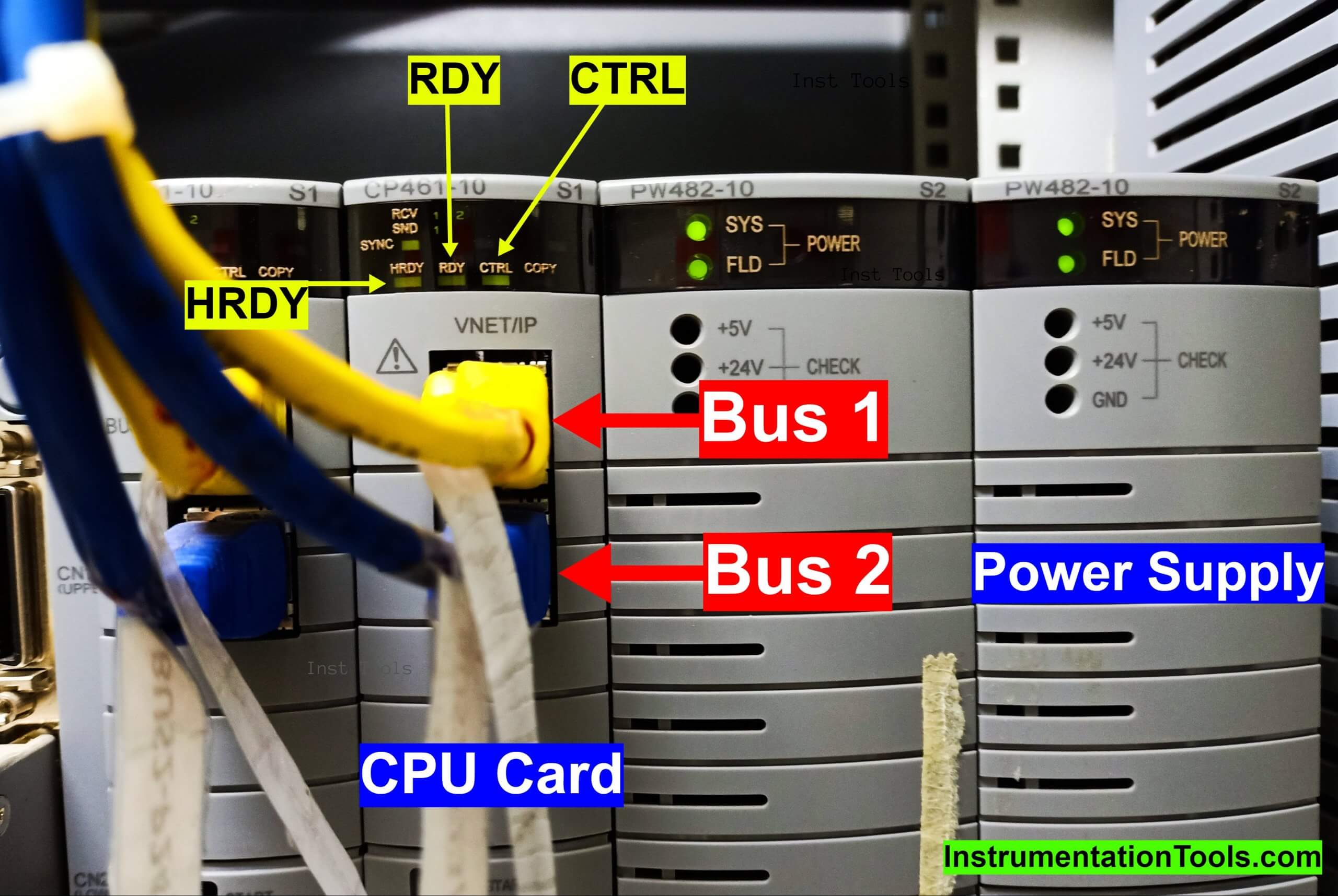
In both CPU cards, HRDY & RDY – LED lamp should glow and in one of the CPU cards CTRL LED should glow.
CTRL LED indicates the controller that is in active state. The HRDY & RDY LED shows the healthiness of the CPU card.
Quiz: Test on DCS
Step 5:
Check the BUS communication status LED in the CPU card.
SEND, RECEIVE of BUS1 and BUS2 LED should blink continuously.
Step 6:
Check for any diagnostic alarms on Processor, redundancy module, IO modules, communication cards, PSU cards.
Step 7:
Check the 5V and 24V DC supply voltages in the power supply card.
Step 8:
Check once all the cooling fans running condition.
Fans are located at the top of the panel and the fan switch will be at the rear side of each panel.
Step 9:
Check the Fan Failure and Temperature Detection Unit (FFTDU) alarm status.
The F-ok, T-ok LED should glow.
If anything is faulty then the fault LED will glow which will be located on the right side of the panel front.
Step 10:
Check the tube light condition by activating the door limit switch which will be on the top corner of each panel.
Step 11:
Check for any loose connections in the panel.
Step 12:
Check the Grounding of the control panel.
Step 13:
Check all the empty slots are properly covered by dummy plates.
(No slots should be open)
Step 14:
Measure the incoming UPS supply voltage.
Step 15:
Measure the utility supply voltage at MCB which will be available on the rear side of the panel.
Step 16:
Check the sealing of spare cable entry slots at bottom of the panel.
Step 17:
Clean all the filters of the panel
Step 18:
Check and ensure cables are properly dressed and cable ducts are covered
Note: All panels must be closed after preventive maintenance activity has been done.
Interest to add any further checks? Share with us through below comments section.
If you liked this article, then please subscribe to our YouTube Channel for Instrumentation, Electrical, PLC, and SCADA video tutorials.
You can also follow us on Facebook and Twitter to receive daily updates.
Read Next:
- DCS Troubleshooting
- Commissioning of DCS System
- DCS Control System Spares
- Yokogawa DCS Architecture
- DCS System Layout


I am Heading Instrumentation / Automation department in Rallis India Limited ( A TATA Enterprise ) which is having Manufacturing units at 5 locations. I am Interested in New letter.
hello