The most basic concept about learning is “If you want to have a deep understanding of any system, you have to go into detail with it”.
If you are a real Automation Engineer you will not be satisfied with the simple basic information about PLCs.
Instead, you will always need to go further for deep details about the CPU of a PLC, how does it work? what is meant by a SCAN CYCLE? and how could this concept (SCAN CYCLE) help us in programming?
If you have already all of these questions in your engineering mind so this post is made special for you … Enjoy.
What is meant by a SCAN CYCLE?
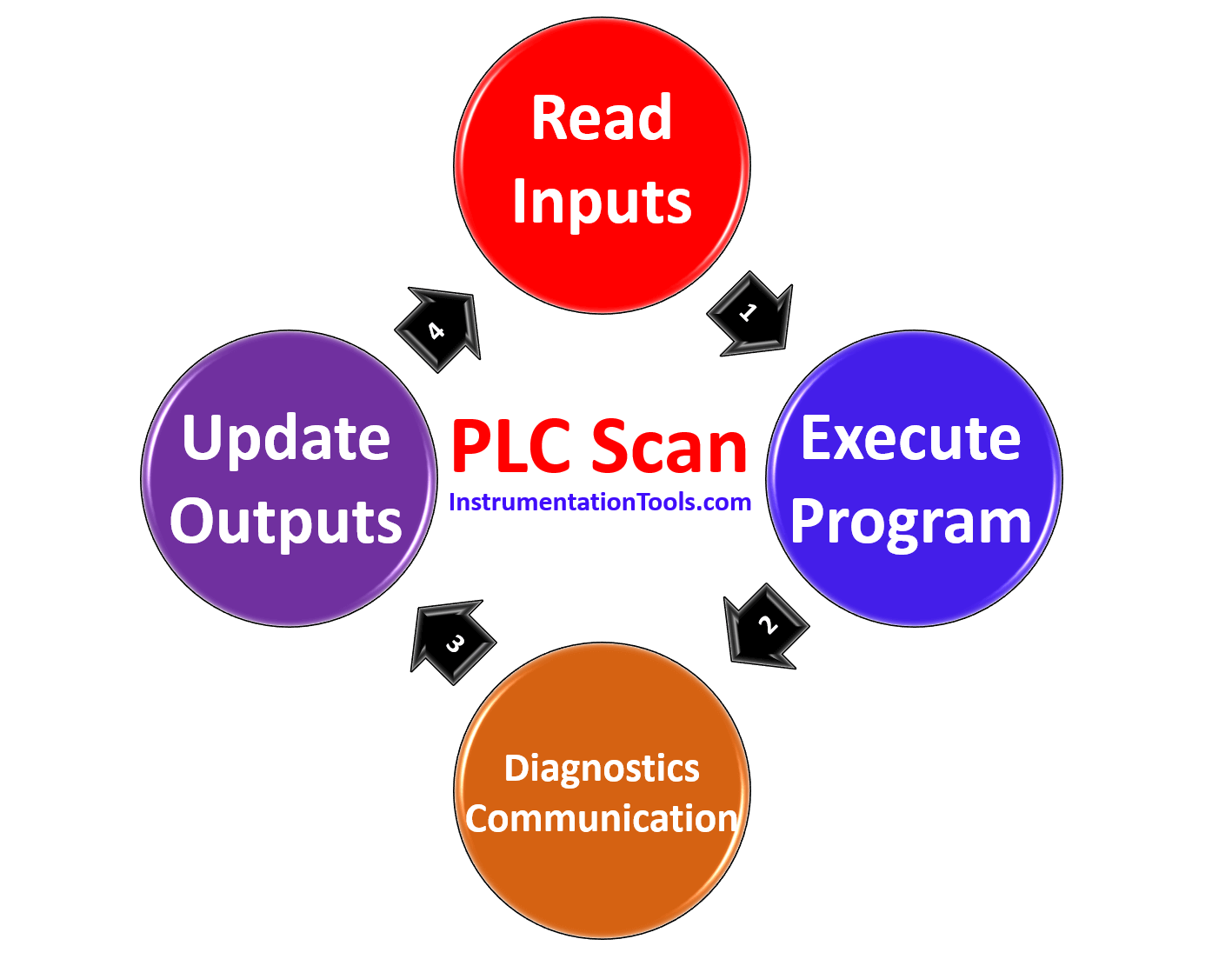
In general, a PLC scan cycle is a repeatable list of executable tasks, the list can vary in size and the tasks can vary in nature and the cycle time varies based on performance and configuration.
It really depends on which PLC you are using. They all do it slightly differently and it’s important to know the difference.
In most PLCs, a scan cycle is the cycle in which the PLC gathers the inputs, runs your PLC program, and then updates the outputs.
This will take some amount of time often measured in milliseconds or microseconds.
Scan Cycle of SIEMENS PLC
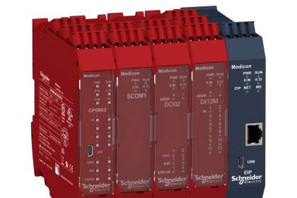
As all of us know that the control system of any electrical panel consists of basic components such as
- a power supply module
- CPU module
- Input/Output cards
- Interfacing module..etc.
The operation and tasks of all of these PLC components are being handled and organized by the CPU module, and for sure the CPU module has specific steps/procedures to control this system.

Inside CPU module of SIEMENS PLC
The following will show the procedures that the CPU performs to execute the scan cycle:
Startup
The first action that a CPU executes when it goes from Stop to Run mode is the STARTUP routine, this routine performs the following tasks:
- The input area of the process image (I memory) is cleared.
- The outputs are initialized with the last value.
- Any interrupt events are queued for processing during RUN mode.
Executing the startup Organization Block (OB100)
As you can see in Fig. (2) after starting up, the CPU will execute the startup OB (OB100).
OB 100 will be executed once, before OB 1 starts, so it is a great place to initialize registers and DBs, set control bits, reset past alarms, and so on before letting the program start.
NOTE:
OB100 will run once just when the PLC boots and will never run again until the next boot.
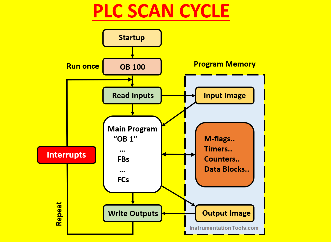
Reading the status of physical Inputs
The program does not scan the signal status on the input signal modules but accesses a memory area in the system memory of the CPU and distributed I/O. This memory area is known as the “process image”.
So, before the system runs the main program it reads the status of the physical inputs and transfers it to the process image (later we will understand why the CPU does not read the input status directly from the input modules.)
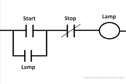
Executing the main program (OB 1)
Now the CPU is ready to perform the main program (ladder logic), this main program is executed through the main OB (OB 1).
In the main OB, you can call the functions (FC) and function blocks (FB), also you can deal with the system memory by using memory flags, timers, and counters.
NOTE:
If any of the FCs or FBs are not being called in the main OB it will not be executed as the scan cycle focuses just on the main OB and what it includes.
After the scan cycle finishes the main OB, the scan cycle will go to copy the updated output status to the process image (output image) to prepare for the next step
Updating the status of physical Outputs
After the user program is executed with all blocks that are called in it, the cycle ends with writing the process image memory (output image) to the output physical modules.
NOTE:
You might be curious “why the CPU does not access the status of the physical I/O module directly?”
The main advantage of accessing the process image is that the CPU will have a consistent image of the process signals for the duration of one program cycle.
If a signal state on an input module changes while the program is being executed, the signal state in the process image is retained until the process image is updated again in the next cycle.
In this way, you can notice that your code will be executed by the more organized method.
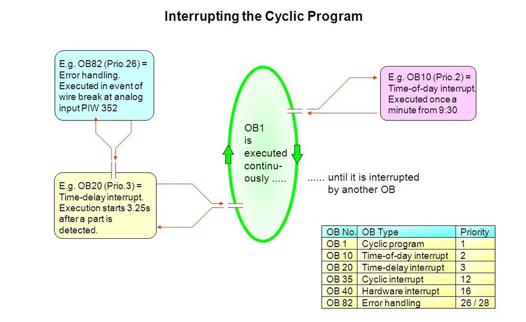
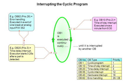
Executing the system Interrupts
An interrupt occurs during any time of the scan cycle, the CPU in this case will make the operating system call the related OB interrupt (OB 121, OB 80, OB86, …), as shown in Fig. (3).
If the related OB was downloaded to the CPU, the CPU will not go to stop mode.
NOTE:
The interrupts do not have a specific position in the scan cycle, once it is initialized it will be executed.
After all of these steps are finished the operating system prepares the CPU to repeat all of these procedures again and again with a high speed reaches to 10:15ms/scan cycle.
If you liked this article, then please subscribe to our YouTube Channel for Instrumentation, Electrical, PLC, and SCADA video tutorials.
You can also follow us on Facebook and Twitter to receive daily updates.
Read Next:


You have matters guys
Thank you very well explain