Inst ToolsInst ToolsInst Tools
  • Courses
  • Automation
    • PLC
    • Control System
    • Safety System
    • Communication
    • Fire & Gas System
  • Instrumentation
    • Design
    • Pressure
    • Temperature
    • Flow
    • Level
    • Vibration
    • Analyzer
    • Control Valve
    • Switch
    • Calibration
    • Erection & Commissioning
  • Interview
    • Instrumentation
    • Electrical
    • Electronics
    • Practical
  • Q&A
    • Instrumentation
    • Control System
    • Electrical
    • Electronics
    • Analog Electronics
    • Digital Electronics
    • Power Electronics
    • Microprocessor
Search
  • Books
  • Software
  • Projects
  • Process
  • Tools
  • Basics
  • Formula
  • Power Plant
  • Root Cause Analysis
  • Electrical Basics
  • Animation
  • Standards
  • 4-20 mA Course
  • Siemens PLC Course
Reading: What is High Integrity Pressure Protection System?
Share
Notification Show More
Font ResizerAa
Inst ToolsInst Tools
Font ResizerAa
  • Courses
  • Design
  • PLC
  • Interview
  • Control System
Search
  • Courses
  • Automation
    • PLC
    • Control System
    • Safety System
    • Communication
    • Fire & Gas System
  • Instrumentation
    • Design
    • Pressure
    • Temperature
    • Flow
    • Level
    • Vibration
    • Analyzer
    • Control Valve
    • Switch
    • Calibration
    • Erection & Commissioning
  • Interview
    • Instrumentation
    • Electrical
    • Electronics
    • Practical
  • Q&A
    • Instrumentation
    • Control System
    • Electrical
    • Electronics
    • Analog Electronics
    • Digital Electronics
    • Power Electronics
    • Microprocessor
Follow US
All rights reserved. Reproduction in whole or in part without written permission is prohibited.
Inst Tools > Blog > Control Systems > What is High Integrity Pressure Protection System?

What is High Integrity Pressure Protection System?

High Integrity Pressure Protection System (HIPPS) is a Safety Instrumented System (SIS) designed to prevent an unsafe condition caused by pressure arising.

Last updated: September 28, 2022 2:43 pm
R Jagan Mohan Rao
Control Systems Safety Instrumented System (SIS)
2 Comments
Share
5 Min Read
SHARE

A high integrity pressure protection system (HIPPS) is a type of safety instrumented system (SIS) designed in accordance with IEC 61508 to prevent over-pressurization of pipelines or vessels in a plant.

Contents
High Integrity Pressure Protection SystemPurpose of HIPPSTraditional SystemModern System

The HIPPS is a distinct application of a safety instrumented system (SIS) designed.

High Integrity Pressure Protection System

hipps

Purpose of HIPPS

The purpose and function of a HIPPS is engineered to isolate and protect the downstream vessels and pipeline equipment against overpressure by closing at the source. Usually, this is done by closing promptly one or more dedicated safety shutoff valves to prevent further pressure rise of the piping downstream from those valves.

A HIPPS is considered as a barricade between high pressure and a low-pressure section of an installation.

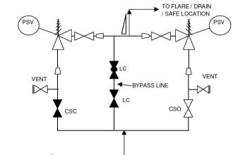
A HIPPS is also commonly referred to as a “high integrity pipeline protection system,” because many HIPPS design/cost studied are associated with field layout pipeline/flowline designs. The above figure shows how a HIPPS is applied in subsea field development.

Traditional System

In traditional systems, overpressure is dealt with by a relief mechanism, which is mounted on individual vessels. Conventional local mounted pressure relief systems have disadvantages such as the release of flammable and toxic process fluids or their combustion gases to the environment.

With increasing environmental awareness, a pressure relief system is not always an acceptable solution. However, because of their simplicity, relatively low cost, and wide availability, conventional relief systems are still often applied in individual pressure vessels.

A relief system will open an alternative outlet for the gas or fluid in the system once a set pressure is exceeded to avoid further increment of pressure in the protected system. This alternative outlet generally leads to a flare or venting system or blowdown to dispose of the excess gas or fluids safely.

A relief system works by removing any excess inflow of the fluids for safe disposal, where a HIPPS aims at stopping the inflow of excess fluids and holding them in the system.

High Integrity Pressure Protection System

Modern System

The HIPPS is designed as a system that detects rising pressure in a flowline and quickly shuts one or more isolation block valves before the pressure can rise too high. This requires a very highly reliable and available system as well as a fast-acting.

Therefore, the main components involved in HIPPS are as follows:

  • Pressure transmitters (also called initiators);
  • Dedicated Logic solvers.
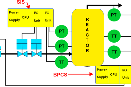
  • Independent HIPPS safety logic from the basic process control system (BPCS).
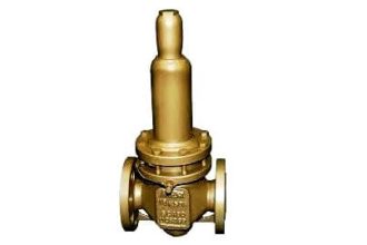
  • Redundant valves (Final Control Elements)

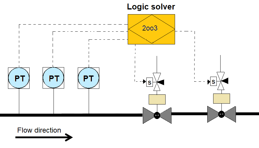
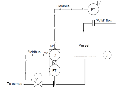
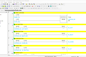
In this system, 3 pressure transmitters as field devices are connected to the logic solver. The logic solver hardware is designed and certified in compliance with the chosen SIL level.

Based on the 2oo3 voting logic, the logic solver will send an output signal to the final control element. The final control elements are two block valves that are in a series move to shut down state and stop the flow to downstream facilities to prevent them from exceeding maximum operating pressure.

The 2oo3 voting with a logic solver system has a high degree of availability and redundancy.

If there is a failure of one transmitter out of three, the final control element receives a control signal from a logic solver with 2 transmitters.

If there is a failure to operate one block valve, another block valve will come in to picture to save facilities from high-pressure protection.

The HIPPS will shut off the source of the high pressure before the design pressure of the system gets over-pressurized, thus preventing loss of containment through the rupture of a pipeline or vessel.

Summary:

  • HIPPS provides environmental protection
  • Minimizes Flare load or blowdown load issues.
  • Risk from catastrophic overpressures can be avoided.
  • Economically viable.

Read Next:

  • Earthing of PLC System
  • Interposing Relay in PLC
  • Different Parts of DCS
  • Instrumentation Design
  • PLC Alarm Acknowledge
Don't Miss Our Updates
Be the first to get exclusive content straight to your email.
We promise not to spam you. You can unsubscribe at any time.
Invalid email address
You've successfully subscribed !

Continue Reading

Types of Noise in Electronics
Switch or Transmitter
Industrial Automation and Control Systems (IACS)
Most Asked Questions on SCADA with Answers
Commissioning Checklists for Industrial Automation Systems
Motor Control Center (MCC) Signal Interface Termination (SIT)
Share This Article
Facebook Whatsapp Whatsapp LinkedIn Copy Link
Share
2 Comments
  • Green Ibanga says:
    December 27, 2017 at 7:01 am

    Dear Resource Manager, Kindly educate me on HOT GAS GENERATOR used in Cement Factory.

    Reply
  • vignesh selvaraj says:
    March 3, 2023 at 12:36 pm

    Yeah great , this article summarizes clearly what is purpose of HIPPS, In addition to that testing intervals and Failure modes can be explained as well.

    Reply

Leave a Reply Cancel reply

Your email address will not be published. Required fields are marked *

Stay Connected

128.3kFollowersLike
69.1kFollowersFollow
208kSubscribersSubscribe
38kFollowersFollow

Categories

Explore More

High Reliability of Safety Instrumented Systems
What is the BACNet Protocol? BACNet IP vs. BACNet MS/TP
How to Do Loop Checks During Plant Pre-Commissioning
What is ERP in Industrial Automation? – Enterprise Resource Planning
Waste Water Control System
Over Pressure Protection Devices
Types of Control Systems
How Modbus is used in Industrial Networks?

Keep Learning

Loop-powered 4-20 mA transmitter

Loop-powered 4-20 mA Transmitter Circuit Voltage drop

Junction Box Wiring

4-20mA Junction Box versus Fieldbus (FF) Junction Box

Difference between SIS, PLC and BPCS Systems

Difference between SIS, PLC and BPCS Systems

PID-Controller-Simulator-graph

PID Controller Tunning Parameters Simulator

PLC or DCS Control System Spares

PLC or DCS Control System Spares

Basics of Emergency Shutdown System

Emergency Shutdown System Philosophy

Control System

The need for automatic controls

Identify Process Variables in P&ID

Identify Process Variables in P&ID

Learn More

Improved Sprocket Segment Bolting to body

A Plant Bucket Elevators chains too short chain lives problem eliminated

Objective Questions on Valves

Objective Questions on Valves

Hydrazine analyzer Working Principle

Hydrazine Analyzer Working Principle

Introduction to GOC controllers

Mitsubishi Electric GOC Controllers

Level Instruments

Level Instruments General Specifications

Pressure Gauge Design

How to Select a Pressure Gauge

Capacitor Principle

Capacitor

PN Junction Questions & Answers

PN Junction Questions & Answers

Follow US
All rights reserved. Reproduction in whole or in part without written permission is prohibited.
Welcome Back!

Sign in to your account

Username or Email Address
Password

Lost your password?