Inst ToolsInst ToolsInst Tools
  • Courses
  • Automation
    • PLC
    • Control System
    • Safety System
    • Communication
    • Fire & Gas System
  • Instrumentation
    • Design
    • Pressure
    • Temperature
    • Flow
    • Level
    • Vibration
    • Analyzer
    • Control Valve
    • Switch
    • Calibration
    • Erection & Commissioning
  • Interview
    • Instrumentation
    • Electrical
    • Electronics
    • Practical
  • Q&A
    • Instrumentation
    • Control System
    • Electrical
    • Electronics
    • Analog Electronics
    • Digital Electronics
    • Power Electronics
    • Microprocessor
Search
  • Books
  • Software
  • Projects
  • Process
  • Tools
  • Basics
  • Formula
  • Power Plant
  • Root Cause Analysis
  • Electrical Basics
  • Animation
  • Standards
  • 4-20 mA Course
  • Siemens PLC Course
Reading: What is a Watchdog Timer in PLC?
Share
Notification Show More
Font ResizerAa
Inst ToolsInst Tools
Font ResizerAa
  • Courses
  • Design
  • PLC
  • Interview
  • Control System
Search
  • Courses
  • Automation
    • PLC
    • Control System
    • Safety System
    • Communication
    • Fire & Gas System
  • Instrumentation
    • Design
    • Pressure
    • Temperature
    • Flow
    • Level
    • Vibration
    • Analyzer
    • Control Valve
    • Switch
    • Calibration
    • Erection & Commissioning
  • Interview
    • Instrumentation
    • Electrical
    • Electronics
    • Practical
  • Q&A
    • Instrumentation
    • Control System
    • Electrical
    • Electronics
    • Analog Electronics
    • Digital Electronics
    • Power Electronics
    • Microprocessor
Follow US
All rights reserved. Reproduction in whole or in part without written permission is prohibited.
Inst Tools > Blog > PLC Tutorials > What is a Watchdog Timer in PLC?

What is a Watchdog Timer in PLC?

Watchdog timer helps to reset the CPU errors which occur during scan time so that the PLC starts working again without any manual reset.

Last updated: March 4, 2021 11:14 am
Editorial Staff
PLC Tutorials
No Comments
Share
3 Min Read
SHARE

In this article, we will learn about a watchdog timer in the Siemens PLC.

As we know that in the PLC when CPU process the logic it takes a certain amount of the time.

The amount of time the CPU takes to process the logic depends on the size of the program.

So, scanning from the first network to the end of the program is called one scan cycle.

For one scan cycle, time must not exceed defined cycle time and amount of time it takes to process the logic.

Watchdog Timer in PLC

To check a cycle time open TIA portal.

In the programming environment go to the main CPU. Do a right-click and click on online and diagnostics.
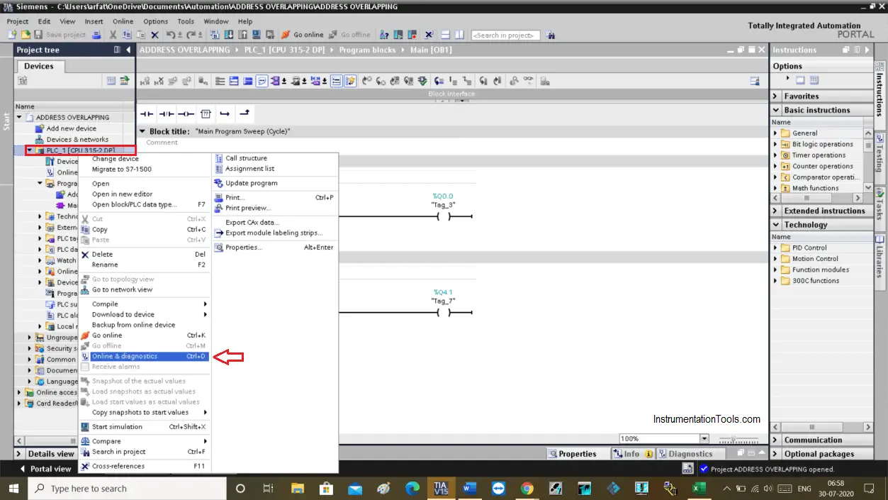
online and diagnostics

The following new window will open up. Choose the cycle time option from it.

One thing to note is that to see cycle time you must have to stay in the online mode. In the offline mode, you won’t see anything.
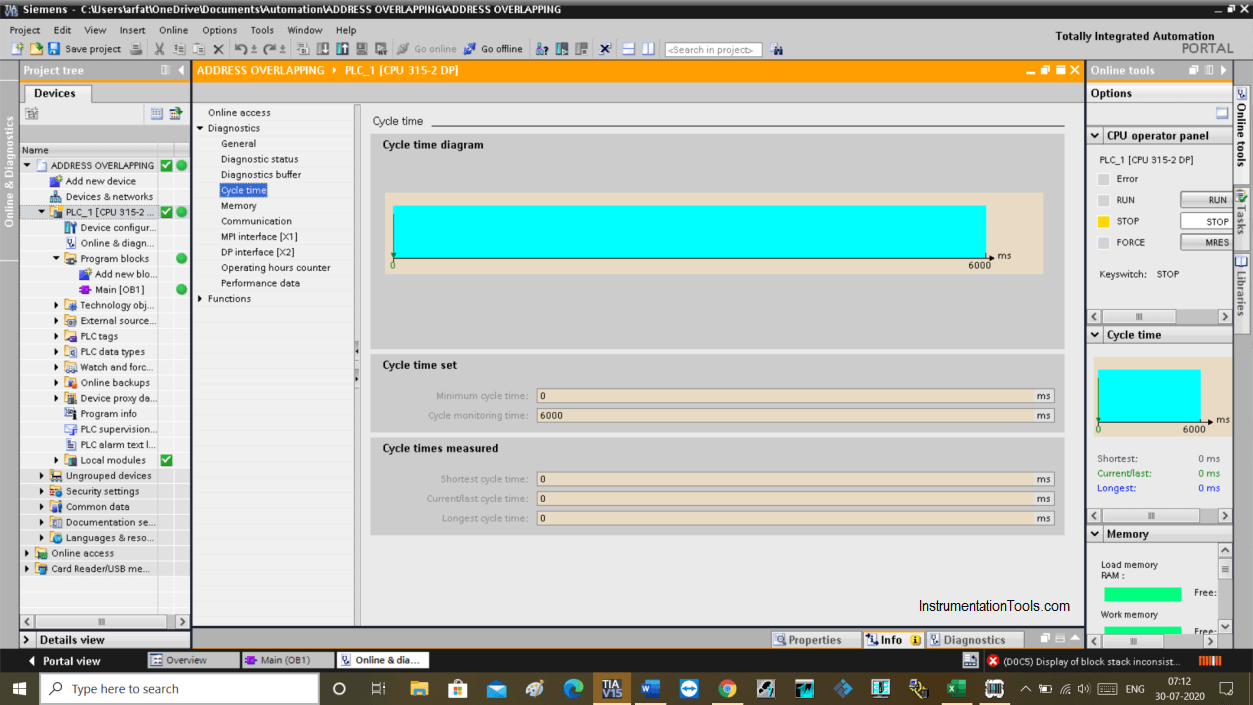
Watchdog Timer in PLC

In the above window, you can see a cycle time. In the cycle time measured tab, you can see a cycle time of the current program.

In the cycle time set option, the maximum time limit Is set to 6000ms means 6 seconds. This is a scan time for one cycle.

So, while execution if cycle time exceeds 6000ms then it generates an error.

Here, it comes to the watchdog timer concept. Based on a scan time when the CPU executes the logic this electronic timer starts to calculate time in the background.

If cycle time exceeds more than defined time, this electronic timer produced an error.

So for this to work, the timer starts timing from the first network and reset its timing at the end of the network.

Due to programming error or any hardware error if the CPU fails to reset the timer then it produces a time-out error.

Watchdog timer helps to reset the CPU when these types of errors occur so that the PLC starts working again without any manual reset. If the errors occur repeatedly then the watchdog timer may not helpful, human intervention is required to troubleshoot the problem.

The scan time varies from cycle to cycle because sometime FCs and FBs are not executed, or due to the manual mode of the PID loops.

This is how watchdog timer works in the background while the execution of the program.

Author: Suhel Patel

If you liked this article, then please subscribe to our YouTube Channel for PLC and SCADA video tutorials.

You can also follow us on Facebook and Twitter to receive daily updates.

Read Next:

  • What is PLC Scan Time?
  • S7 1500 PLC Simulator
  • Siemens Peripheral IOs
  • Basics of DDE Protocol
  • Trends in SCADA System
Don't Miss Our Updates
Be the first to get exclusive content straight to your email.
We promise not to spam you. You can unsubscribe at any time.
Invalid email address
You've successfully subscribed !

Continue Reading

Data Handling Instructions in PLC Programming
Pump and Mixer Operations Example: PLC Timer-Based Control
How to Communicate with Excel from Intouch SCADA?
OB1 – Main Cyclic Organization Block in TIA Portal
Types of Interlocks
How a PLC do the Scaling for a Sensor ?
Share This Article
Facebook Whatsapp Whatsapp LinkedIn Copy Link
Share
Leave a Comment

Leave a Reply Cancel reply

Your email address will not be published. Required fields are marked *

Stay Connected

128.3kFollowersLike
69.1kFollowersFollow
208kSubscribersSubscribe
38kFollowersFollow

Categories

Explore More

From Boolean Algebra to PLC Logic
Communication Processor Module in Siemens PLC
PLC Automatic Irrigation System
Examples of SCADA and PLC Configuration Systems
PLC Packing Machine Control System Program in XG5000
How to Use Diagnostic Buffer for SIEMENS PLC?
Types of Noise in Electronics
Sorting & Distribution Line PLC Programming – Advanced Logic

Keep Learning

PLC Data Logging and Transmission

Moving Data between PLCs – Siemens Basics – TSEND TRCV

PROFIBUS is also a Master Slave protocol

Compare Modbus, Fieldbus, and Profibus

Peripheral Inputs and Outputs in Siemens PLC

Peripheral Inputs and Outputs in Siemens PLC

Create Ladder Diagram from Boolean Logic

Create Ladder Diagram from Boolean Logic

Types of Interrupts Organization Blocks in Tia Portal

Types of Interrupt OB in Siemens Tia Portal

Sequential Timer Control of Lamps

Schneider PLC Example: Control Lamps Sequences

PLC Stop - Start Circuit

Introduction to PLC Ladder Diagrams

Operator Interface for SCADA System

Operator Interface for SCADA System

Learn More

How to Troubleshoot Control Valve - Problems and Solutions

How to Troubleshoot Control Valve? – Problems and Solutions

gas chromatograph principle

Online Gas Chromatograph Principle

Pipeline Pig Detector

What are Non-Intrusive Pig Signallers or Pig Detectors?

Fieldbus Segment

Basics of Foundation Fieldbus

Design Logic Diagrams with Standard Formats for Process Control

Design Logic Diagrams with Standard Formats for Process Control

VFD Braking

DC Injection Braking in VFD

Troubleshooting Fluid Systems Pressure Changes

Troubleshooting Fluid Systems Pressure Changes

Active Electrical Filters

Active Electrical Filters Objective Questions

Follow US
All rights reserved. Reproduction in whole or in part without written permission is prohibited.
Welcome Back!

Sign in to your account

Username or Email Address
Password

Lost your password?