DCS (Distributed Control System) commissioning is a critical phase in the lifecycle of a process plant or facility. Commissioning ensures that the DCS system is set up correctly, functions as designed, and is ready for operation. The DCS manages and controls various equipment, processes, and systems in an industry.
Physical Checks
- All civil works required for DCS cabinet installation shall be completed.
- Ensure painting work is completed in the area.
- Ensure completion of false flooring in the area, if applicable
- Ensure proper lighting available in the control room and Panel Room.
- Ensure HVAC is commissioned for the area or ensure proper ventilation in the area.
- Ensure proper installation and fixing of the panels at the location as per GA drawing.
- Check and ensure anti-vibration pads of the panels are in place.
- Check that dust filter on louvers is clean, for indoor panels
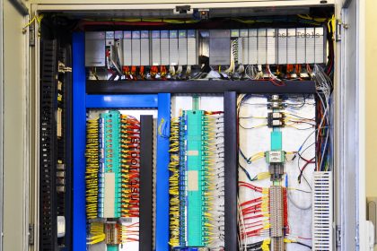
- Check DCS panels for the physical damage – Door lock, door limit switch, Fans, Tube lights, internal cables, MCBs, isolators, modules, racks, controllers, prefab cables, etc.
- Check all the components of the panel as per BOM. Check for loose supplied items.
- Check and verify all hardware like Engineering and operator station as per BOM.
Pre-Requisites
- Ensure availability of approved DCS GA drawings, System Architecture Drawing, Network interconnection, Power wiring and distribution, Earthing wiring drawings, Functional design Specification for DCS, I/O list/nest loading, Instrument list, Bill of Material, Cable termination schedule, P&ID Drawings, Control narrative/process description, logic diagram, FAT Reports, etc.
- Ensure availability of instrumentation technicians, engineers, programmers, and tools – like Screw Driver, Tester, Digital Multimeter, Insulation resistance tester, Earth pit resistance checker, 4-20 mA source, HART communicator, Loop check tester, short links, etc.
- Ensure UPS (redundant) and Non-UPS (Utility) power supply is available. Before charging the DCS check whether UPS and battery banks commissioning is completed.
- Operator work Station (OWS), Engineering work station (EWS) HMI are ready with installed software as per system requirement. Check Antivirus is installed.
- Ensure the Latest backup of FAT logic, Graphics configuration available.
- Check the validity of license software for HMI and Logic software/configuration software.
- Electronic/instrument (IE) and Intrinsically Safe (IS) earth pit/grid is ready as per installation drawing. Cabling from earth pit or IS Earth Grid to DCS Panel is completed. Isolation between instrument Earth and panel earth/ cabinet body earth/system earth (SE).
- Master clock signal is available
- Test schedule, agenda, roles and responsibility matrix should be available.
Safety
- The area under commissioning shall be tagged and PTW (Permit to Work) is issued/available.
- To protect personnel and the equipment in the area of commissioning, “area restrictions” shall be displayed/tagged.
- Use of PPE is mandatory
Brief DCS Commissioning Steps
Below is a general guideline to have an overview of commissioning steps.
One has to follow agreed templates/checklists/procedures or protocols for the entire DCS system commissioning.
Cabinet and console furniture hardware check
Make, model, color, thickness, dimensions, component mounting, safety sticker.
Verification of component inside the cabinet/console and its specification w.r.t approved documents.
Labeling check
It is to verify that the cabinet nameplates and component labels.
All components inside the cabinet (Controllers, firewalls, switches, I/O modules, barriers/isolators, racks/nodes, Power supply modules, terminals & its size, relay boards, Safety earth, instrument earth, MCBs, MCB rating, sockets, cross ferrule, patch panels, convertors, servers, etc) shall be properly labeled so that can be easily identified.
The workmanship is verified.
Internal Wiring check
It is to verify that the cabinet internal wirings are as per the project specification and approved drawings.
AC power, DC power, signals (AI, AO, DI, DO, RTD, TC, Special modules) internal wiring, earthing wire color, size, duct color.
Continuity check.
MCBs / isolators check.
Fuse rating check.
Cable dressing check.
Main cable installation, termination, gland plates, and sealing shall be verified.
Nest loading and I/O assignment check
It is to verify controllers, racks, slots, modules, etc
System startup check
This includes UPS and non-UPS Power check, Earthing check.
When required parameters are within tolerance then power on of system is done step by step.
Ensure that all components automatically boot up and components are in healthy condition.
Cabinet Alarm Check
It is to verify the cabinet alarm functionality when a hardware failure occurs.
Verification of temperature switch, fan modules, Power supply modules, etc.
This should be used for cabinet diagnosis purpose.
Redundancy Check
It is to verify that system operation is uninterrupted when the active hardware fails.
This test is conducted for
- redundant power supply (bulk and system power supply),
- redundant controllers/ CPU,
- Redundant communication buses(I/O modules to nodes/racks,
- nodes to controllers,
- controllers to switches,
- switches to stations,
- redundant I/O modules,
- redundant servers,
- GPS systems, etc
System Architecture Check
It is to verify that all components are completely networked.
Interconnection of components to be verified.
Ensure that all IP addresses are properly configured uniquely for each station including printers.
Time Synchronization Check
It is to verify time matches & synchronizes with the GPS time.
This includes visual checking of
- GPS antennas,
- GPS receivers,
- NTP/SNTP switches, and their power on.
GPS time shall appear in all synchronized stations.
Software License Check
It is to check all applicable licenses for Workstation (Operator, engineering) and its applications like a logic builder, HMI, reports, server licenses, etc.
This shall be documented as part of BOM and verified in each station.
Graphic Check
Graphics layouts checking w.r.t P&ID, shape, size, backgrounds, and icon color when status changes (red, green, blue, etc).
Faceplate, tagging, the description shall be checked.
Functionally as per the requirement of the process (Auto, manual, local, remote, bypass, etc) shall be implemented.
Few activities can be done in parallel to I/O loop checking.
I/O Loop check
I/O Assignment is configured properly in PCS. Marshalling wiring and termination matches with I/O allocation.
This can be done either cold loop or hot loop testing. Cold loop checking means loop checking is done without powering on instruments.
Only wiring continuity is checked from field to Junction Box and then to the control room. Hot loop checking is done by powering the instrument.
At the site, it is good to perform a cold loop check first and then perform a hot loop check with actual instruments and interfaces.
All the I/Os connected to the system is checked.
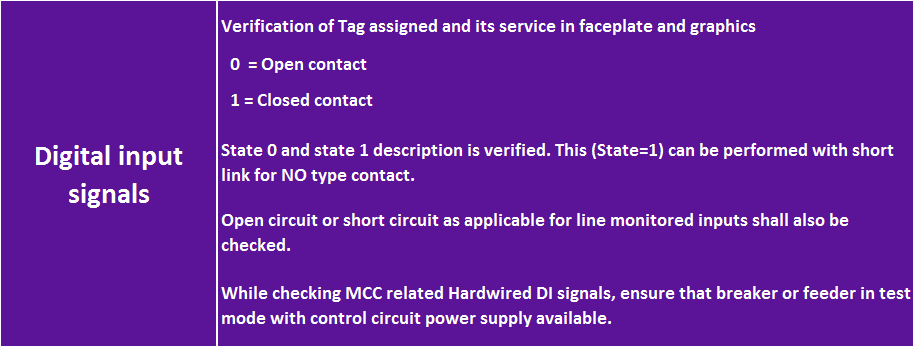
Digital Input Signals
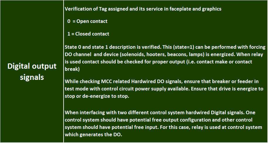
Digital Output Signals
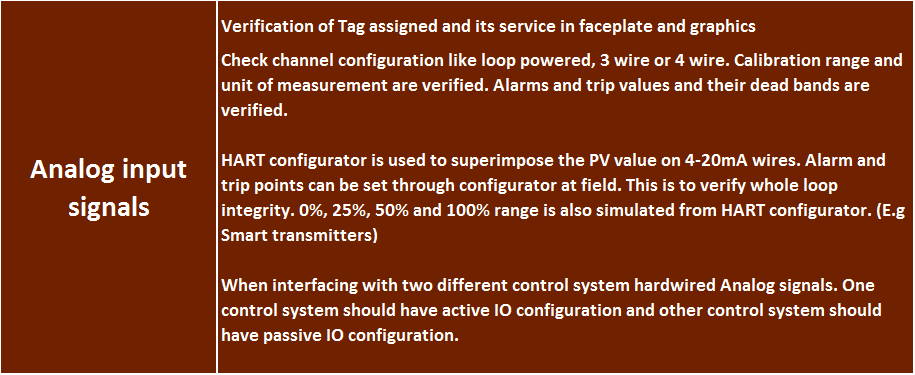
Analog Input Signals
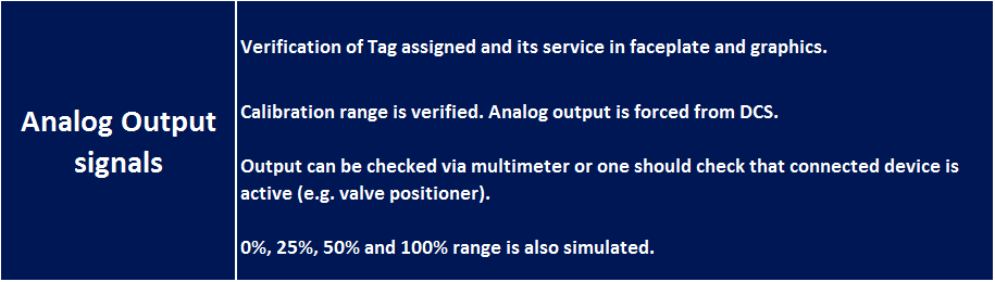
Analog Output Signals
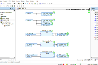
Logic Check
It is to verify Control Algorithm Implementation with reference to logic diagrams, functional schematics, or control narrative.
Nest loading is also important to know associated I/O tags and their addresses.
Alarm and trip value to be verified. Closed-loop control (PID parameters) and controller action to be verified.
Logical opening/closing of valves/dampers, starting or stopping of drives (pumps, compressors, etc) to be verified.
All interlocks, start permissive and first-out logics are tested.
Trend & Control Group, Log Reports
It is to verify Trend Input, Historical message, Alarm summary, SOE.
Trend group is necessary during logic/ loop testing and plant operation to know the accurate functioning of relevant inputs and outputs.
Log reports are necessary to know the overall inputs, outputs, and performance of the plant and to plan the resources and future maintenance. Along with this, printer functionality is also tested.
Controller Loading Check
It is to verify Controller loading shall not be more than 60 %.
As some spare capacity is required for future expansion or modification.
Online / Offline Program Loading
It is to verify system behavior Online or offline Configuration/Modification from the engineering station.
System vendors detailed procedure shall be followed while doing so.
Scan Time Check
It is to demonstrate that controller’s actual scan time is within the project specification. This is more relevant to the safety system.
However, this can also be performed for DCS.
Login Users and their access
It is to verify what type of access the operator/engineer or manager has.
Communication with 3rd party systems
It is to verify system communication with third party systems.
Usually, this communication will be Modbus RTU (RS 485), Modbus TCP/IP, OPC, and IEC 61850 for electrical systems.
Configurations, software, and hardware are verified.
Graphics and logics testing is done.
Modification
Change management procedures to be followed and documented.
Spare Check
It is to verify the installed spares within the system, commissioning spares, operational spares as per contract requirement.
Sometimes this also includes Spare space checking inside the cabinet, Hard drive space, etc.
Miscellaneous Checks
depending upon project scope of work other functionality of hardware or software can be checked like
- Asset management,
- cybersecurity,
- alarm rationalization,
- Partial stroke testing,
- HART multiplexer (master and slaves), etc
Punch list
It is to document all non-conformances or faults found on the system during the acceptance test along with their corrective actions.
At the site, one can have an overview of open punch points during the FAT test at vendor works. These non-conformances can be attended as per the agreed schedule and resources.
Reports
once all the tests are completed, all the relevant test reports shall be preserved and handed over to end-user.
All the changes in affected drawings, documents, configuration shall be properly marked for As-built documentation.
Handover
once all the non-conformances are clear, a certain performance period is over, DCS can be handed over to the end-user.
It is essential to have proper training in the DCS system before working on the same.
Author: Jatin Katrodiya
If you liked this article, then please subscribe to our YouTube Channel for PLC and SCADA video tutorials.
You can also follow us on Facebook and Twitter to receive daily updates.


Nice brief knowledge for reference to commissioning purpose.
Please share me on my mail address
Thanks n regards.
Good write-up. But most of these activities should be done during a Factory Acceptance Tests( FAT) .
FAT ensures proper working of DCS ( like redundancy tests, I/O tests, mock loop tests involving simulated input/ output values driven by a PC, power redundancy tests, software logic and/or control loop parameters be it P+I or PID controller assignment, Range and alarm value settings, alarm printer working including data stamping where required, protocol printer testing by observing PC generated cyclical input value correctness, checking of calculation / functional blocks, advanced controls working check with PC simulated input variations, scan frequency setting testing etc).
A fully rehearsed complete FAT as mentioned above need very little activities at site. Every DCS manufacturer provides a PC to facilitate such testing as part of their FAT routine.
FAT is also witnessed by the client and/ or their authorized Project Management Contractor to ensure smooth site commissioning.
EPC contractor who delivers the DCS or other agencies entrusted with delivery of DCS hardware+Configuration software furnishes in advance the FAT procedure which should be approved by the Client and/ or their PMC.
Sometimes it involves process licensor ( if EPC contractor is not a supplier of process license).
Site Acceptance Tests ( usually involves all activities other than FAT activities as mentioned above) . This is part of Mechanical Completion for the complete plant.
This was my personal experience which had ensured multiple successful start-up’s which essential for any LumpSum contracts to avoid paying any penalties for delay in plant delivery inclusive of successful plant acceptance certification.
Both FAT and SAT is required to be attended by process engineers from EPC contractor as well as licensor’s presence together client and / or their PMC.
It was nicely represented through the description.
However, it is suggested to keep a Checklist where the activities are specified with the attendes approval, a kind of Document / Excel Sheet with Individual activity.
Also there shall be fucntional logic verification done based on P&ID’s, Cause & Effect / Logic Documents. which shall be a controlled through a no. of sheets agreed with the clients / customers.
Very helpful guidelines.
Could you share a pdf copy with me?
Thanks in advance.
Best regards.
Hi very nice explanation please share me pdf file if Available