Instrumentation maintenance engineer often hears about process value mismatch from field transmitter display reading and control room DCS/PLC reading.
Generally we see the readings mismatch between field & DCS happens due to the improper configuration either at transmitter or in control room (DCS/PLC).
Readings Mismatch between Field & Control Room ?

For example : Operations team informed that a temperature transmitter shows 112 Deg C reading in the field local display and 89.6 Deg C in the control room HMI/SCADA. Then Instrumentation engineer checked & found that Field Transmitter configured range is 0 to 250 Deg C whereas in DCS the configured range is 0 to 200 Deg C. Because of this improper configuration, we have mismatch in readings between field & control room.
Note : use Online Inst Calculator to do conversions like pv to mA or similar
Fine, Now lets assume that the configurations are properly done in field transmitter and in DCS but still we are getting some difference in readings between field & DCS. What happens ?
This may happens because of 4-20mA loop current drop also. In this article i am discussing about the impact of loop current drop in Field & Control room readings.
The 4-20mA loop current drop may happens due to the following :
- Little bit High Main cable / Branch cable resistance : Theoretically there will be NO current drop in the loop but sometimes (practically on different rare situations) there will be small amount of current drop can be seen due to cable problems like high resistance, insulation damage, noise, emf etc.
- Range Mismatch
- Ground Loops
- Improper Transmitter Analog output card calibration/configuration
- DCS/PLC Analog Input card Resolution ( Very low Possibility of this error )
- DCS/PLC Analog input card channel calibration (Very low Possibility of this error )
- Loose connections in the loop
- Rusted components or terminals
Above listed are the some possibilities for 4-20mA loop current drop.
Theoretically loop current will be same in the total loop but we sometimes found a very small amount of loop current drop. Now the question ” is there any impact of this loop current drop on process variable readings ? ” we will discuss below.
Now another question also will come into your mind that How to check the 4-20mA Loop current Drop is there or not ? or loop current drop is the problem or any other things are causing the reading mismatch between field & control room ?
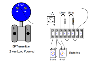
First thing to do is measure the existing loop current. connect a multimeter in series with the loop and note the loop current value, for example say multimeter displays 5.99mA. Good, we got the loop current reading but it is the right value ? Lets check.
Well, you NO need to use any formulas or calculations to calculate the Actual Transmitter Output current with respect to present PV, LRV & URV values. ( we can also find out the actual loop current by using process variable to 4-20mA conversion formula also).
Simply connect your HART communicator to the transmitter and check Analog Output Current reading in HART display, say it shows 6.00mA. Please remember that if there is loop current drop also, this HART display shows correct reading as this value directly coming from transmitter processor/cpu.
Even if transmitter inbuilt digital to analog card not working properly also the HART Display shows the correct reading in most cases as it taking the value from transmitter processor/cpu and not from transmitter D/A card.
Now we got these readings :
- HART display shows 6.00 mA
- Multimeter shows 5.99 mA
The difference between Actual reading (HART Display) and Present reading (multimeter) is 0.01mA. Now a quick question comes into your mind : What is the impact of this very small amount of 4-20mA loop current drop ? is this important to consider or negligible ? we will see with examples below.
Example 1 :
A Pressure transmitter having a range of 0 to 10 kg/cm2 installed in a pipeline. The present value indicating by the transmitter display/ local display reading is 1.25 kg/cm2 and 1.24375 kg/cm2 displaying in Control room. Why there is a difference and What happens ?
we will apply above discussed parameters here i.e. some pressure is there in the pipeline and HART display shows 6mA and multimeter connected in the loop showing 5.99mA.
Also note that HART local display shows process variable reading based on 6mA or transmitter processor/cpu value, so the local display shows 1.25 kg/cm2 ( calculate equivalent process variable from 6mA).
Consider there is a small amount of loop current drop ( assume 0.01mA), so multimeter shows 5.99mA, so DCS/PLC Analog input card also receives 5.99mA instead of 6mA. when you convert 5.99mA to equivalent process variable, the control room shows 1.24375 kg/cm2, if you apply round number, the SCADA graphics shows 1.244 kg/cm2.
Now the difference between field reading and control room reading is 0.006 kg/cm2. Percentage of error is 0.06%.
if you consider one decimal number then field reading is 1.2 and control reading also 1.2, so both are same, fine. Percentage of error is 0 %. Looks good.
same way if you consider two decimal numbers then field reading is 1.25 and control room reading is 1.24, so there will be error of 0.01 kg/cm2. Percentage of error is 0.1%.
Again consider three decimal numbers then field reading is 1.250 kg/cm2 and control reading is 1.244, so there will be error of 0.006 kg/cm2. Percentage of error is 0.06%.
Lets see the comparison without rounding of number in control room : Field reading is 1.25 kg/cm2 and control room reading is 1.24375 kg/cm2, so there will be error of 0.00625 kg/cm2. Percentage of error is 0.0625%.
Finally our error percentage varying from 0 % to 0.0625 % ( 0 to 0.00625 kg/cm2 in terms of process value ) depending on number of decimals of the transmitter & DCS readings. In this example, Everyone says that it is OK with the readings as there is no much difference with the readings ( considering transmitter loop is non-critical ).
Lets see the same situation with another example
Example 2 :
A Flare flow meter having a range of 0 to 1,50,000 kg/hr. we will apply above discussed parameters here i.e. HART display shows 6mA and multimeter showing 5.99mA.
HART Display @ 6mA Shows 18750 kg/hr
Process value Multimeter in loop measures 5.99mA, When we calculate equivalent process value then we have 18656.25 kg/hr
Now the difference between field reading and control room reading is 93.75 kg/hr. approx Percentage of error is 0.06%. Here percentage of error remains same but there is a considerable amount of loss in process value. The main reason for this is due to higher span range of transmitter. Well in this case, we cannot neglect the small amount of loop current drop.
Remember that there will be no impact of loop current drop in field transmitter display (considering transmitter has inbuilt display) as it getting the value from internal transmitter processor/cpu and definitely there will be impact in control room reading.
Also if you connect a external loop power indicator in series with the loop then this loop power indicator reading also effected as same as control room because loop power indicator & control room have same input i.e. 5.99mA as per our example.
we considered 0.01mA loop current drop and seen the two examples & their impact on process reading in field & control room. Now take a small assignment yourself and Consider 0.05mA & 0.1mA loop current drop and observe the impact on process variable readings in field & control room.
I hope you also faced the readings mismatch between field & control room related problems.
Lets share with us what was the problem & how you solved it.
Share via comments…
Happy learning & sharing @ InstrumentationTools.com
If you liked this article, then please subscribe to our YouTube Channel for PLC and SCADA video tutorials.
You can also follow us on Facebook and Twitter to receive daily updates.
Read Next:


thanks very helpfull
Thank you Sir.
Good, information sir .
Dear sir
I’m e&i graduated actually now I’m working in paint shop in One automotive engineering company in graduated engineer trainee After I got experience can I go for our core Field like process automation Plz clear my doubt awaiting
Very instructive!
If current recieved in the DCS end is less than it should be it is usually due to high resistance saturating the current, or additional current due to a ground loop
This, and other problems you mentioned for 4-20 mA (and other analog signals) can be avoided by using real-time digital communication instead, such as FOUNDATION fieldbus.
To Jonas point about ground loops, this is most common with 4 wire type transmitters where the power source is 110 vac and the output is 4-20 mA.
I have seen loops with greater than 100 mA output to DCS/PLC as a result of ground loops.
I agree with Jonas. With FOUNDATION fieldbus the process variable reported by the transmitter is exactly the same as the process variable read at the control room EVERY cycle, even to 6-decimal precision. We don’t need that kind of precision but it just proves what you read is what you get.
For existing installations, I get it. 4-20mA is everywhere and I appreciate articles like this that educate how to deal with the idiosyncrasies of each technology, but for new installations it continues to baffle me why users don’t choose digital field networks over 4-20mA to avoid these shortcomings.
Problem with using digital communication is absence of standardisation. Once you have selected a particular technology you are tied in.
This happens all too often but the different ranges of the DCS/PLC versus the field instrument is only one of the possible causes. One common range difference is a DCS/PLC set to 0-20 ma when the transmitter is outputting 4-20 ma.
The most common reason for a discrepancy between field device and DCS/PLC is a different ground potential at the transmitter then at the DCS/PLC, most of the time the ground is floating at the transmitter and the ground is always at the DCS/PLC end of the loop. More common in self powered instruments where an isolator is sometimes used to interrupt ground loop.
If correct calibration has been done, there is also the possible difference of resolution of the analog input, the accuracy of the instrument, and the resolution of the scaling. These all have the possibility of adding to the error of control room reading compared to the field instrument.
Thanks a lot for the assistance ,, usefull ,no words
Dear sir.
Thank you so much for this article. This is very useful article.
Sir could build the instrumentationtools calculation application for iPhone.
It is very useful for every instrumentation guys thank you very much.
Great article! Thank you for writing it.
It reminds me of an article that I wrote 3 years ago. It is still posted on Profinews called ‘Is PROFIBUS more accurate then 4-20 mA’. I have just posted two video’s that you might find interesting on my youtube channel (Comms guy) about the problem with 4-20 mA.
Dear sir
In field mass flow meter showing 0 kg/hr
But in dcs it is showing 20 kg/hr
My range is 0 to 6500 kg/hr
When feed ma from source
For 4 ma it is showing 20 kg hr
At 3.8 ma oly it is showing 0 kg/hr
When it is 4.1 ma it is showing 40 kg/hr which is correct wit my range..
Why for 4 ma I am getting 20 kg/hr
Hi,
It is difficult to guess the issue. Hope DCS configuration is correct.
Also when feeding 4mA from field, measure the loop current with multimeter to cross-check, if it shows 4mA then it is fine otherwise check it.
As you are getting the issue when feeding milli amperes, so you can leave the field and concentrate on DCS.
Feed the mA in the barrier and check again, if issue solves then problem with the cables like ground loops, mutual induction, high resistance, voltage drop etc.
If you have issue with the above step, then check DCS configuration again, change barrier or AI channel and check gain.
There will be many factors. i am sharing the general issues.
Share your solution with us after solving it.
Dear Sir,
I have installed a new turbidity analyzer (ROSE MOUNT 1056) and calibrated in standard mode with 20 NTU solution.
But i am getting some difference value when it is in process..
when i am taking inlet treated water sample and check turbidity in portable meter it gives the 2.75,ntu but when the 1056 is in online it gives 3.85ntu,
why this difference is coming.. please suggest me what i can do?
Thank you for remind me to the old memories. I started to memorising back the one that i done before. Thank you and had a wonderful day.
i am not sure about the way you calculate your percentage error , why do you multiply the difference direct with 100. Why not use the difference divided by the expected value and you then multiply by 100?
There’s a big mismatch in the the readings of control room and pressure transmitter the control room is showing -1.9 nm3/hr and the transmitter is showing 350 nm3/hr