Inst ToolsInst ToolsInst Tools
  • Courses
  • Automation
    • PLC
    • Control System
    • Safety System
    • Communication
    • Fire & Gas System
  • Instrumentation
    • Design
    • Pressure
    • Temperature
    • Flow
    • Level
    • Vibration
    • Analyzer
    • Control Valve
    • Switch
    • Calibration
    • Erection & Commissioning
  • Interview
    • Instrumentation
    • Electrical
    • Electronics
    • Practical
  • Q&A
    • Instrumentation
    • Control System
    • Electrical
    • Electronics
    • Analog Electronics
    • Digital Electronics
    • Power Electronics
    • Microprocessor
  • Request
Search
  • Books
  • Software
  • Projects
  • Process
  • Tools
  • Basics
  • Formula
  • Power Plant
  • Root Cause Analysis
  • Electrical Basics
  • Animation
  • Standards
  • 4-20 mA Course
  • Siemens PLC Course
Reading: Ethernet Bus Animation
Share
Notification Show More
Font ResizerAa
Inst ToolsInst Tools
Font ResizerAa
  • Courses
  • Design
  • PLC
  • Interview
  • Control System
Search
  • Courses
  • Automation
    • PLC
    • Control System
    • Safety System
    • Communication
    • Fire & Gas System
  • Instrumentation
    • Design
    • Pressure
    • Temperature
    • Flow
    • Level
    • Vibration
    • Analyzer
    • Control Valve
    • Switch
    • Calibration
    • Erection & Commissioning
  • Interview
    • Instrumentation
    • Electrical
    • Electronics
    • Practical
  • Q&A
    • Instrumentation
    • Control System
    • Electrical
    • Electronics
    • Analog Electronics
    • Digital Electronics
    • Power Electronics
    • Microprocessor
  • Request
Follow US
All rights reserved. Reproduction in whole or in part without written permission is prohibited.
Inst Tools > Blog > Electronics Animation > Ethernet Bus Animation

Ethernet Bus Animation

Last updated: April 29, 2018 2:14 pm
Editorial Staff
Electronics Animation
No Comments
Share
3 Min Read
SHARE

Ethernet Bus:

Ethernet Bus Animation

This is a coax based Ethernet network where all machines are daisy chained using RG58 coaxial cable (sometime referred to as Thin Ethernet or Thin-net).

Machine 2 wants to send a message to machine 4, but first it ‘listens’ to make sure no one else is using the network.

Collision :

This animation starts with machine 2 and machine 5 both trying to transmit simultaneously.

Ethernet Bus Collision Animation.gif
Ethernet Bus Collision Animation

The resulting collision destroys both signals and each machine knows this has happened because they do not ‘hear’ their own transmission within a given period of time (this time period is the propagation delay and is equivalent to the time it takes for a signal to travel to the furthest part of the network and back again).

Using Hub:

An Ethernet hub changes the topology from a ‘bus’ to a ‘star wired bus’, here’s how it works.
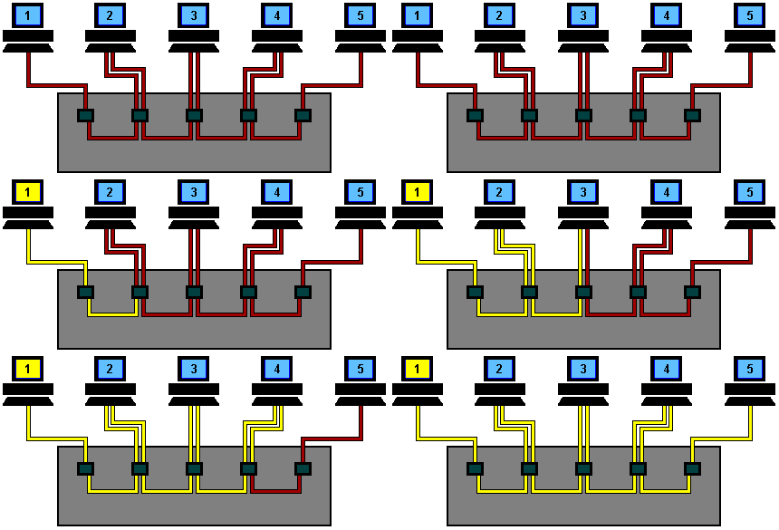
Ethernet hub Animation

Again, machine 1 is transmitting data to machine 4, but this time the signal travels in and out of the hub to each of the other machines.

As you can see, it is still possible for collisions to occur but hubs have the advantage of centralised wiring, and they can automatically bypass any ports that are disconnected or have a cabling fault. This makes the network much more fault tolerant than a coax based system where disconnecting a single connection will bring the whole network down.

Using Switch:

To overcome the problem of collisions and other effects on network speed, a switch is used.
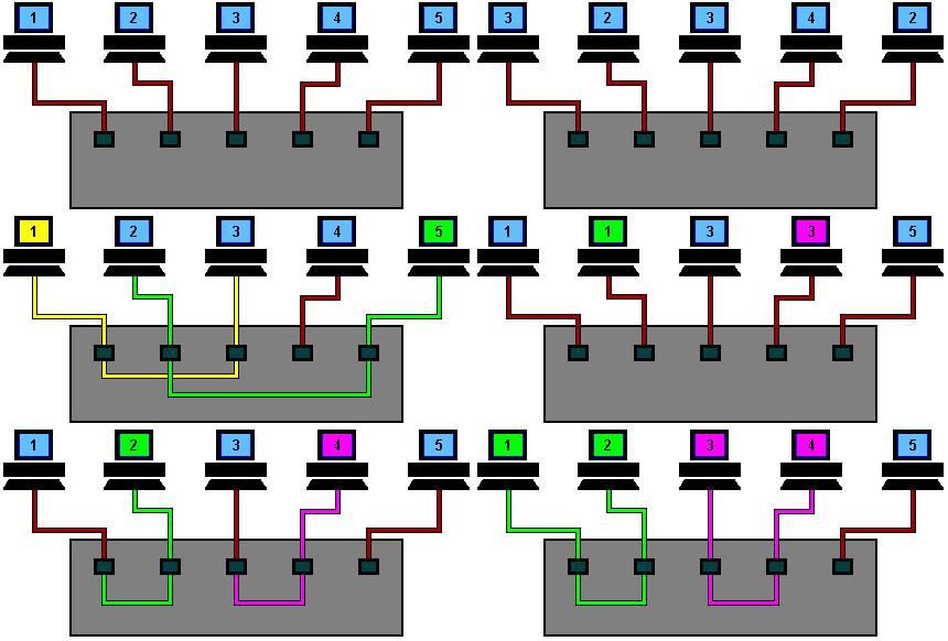
Ethernet Switch Animation

With a switch, machines can transmit simultaneously, in this case 1 & 5 first, and then 2 & 4. As you can see, the switch reads the destination addresses and ‘switches’ the signals directly to the recipients without broadcasting to all of the machines on the network.

This ‘point to point’ switching alleviates the problems associated with collisions and considerably improves network speed.

Don't Miss Our Updates
Be the first to get exclusive content straight to your email.
We promise not to spam you. You can unsubscribe at any time.
Invalid email address
You've successfully subscribed !

Continue Reading

Bridge Rectifier Working Animation
Transistor as a Switch Working Principle
Optocouplers Working Principle
Full Wave Bridge Rectifier Operation
Center Tapped Full Wave Rectifier Operation
Half Wave Rectifier Principle
Share This Article
Facebook Whatsapp Whatsapp LinkedIn Copy Link
Share
Leave a Comment

Leave a Reply Cancel reply

Your email address will not be published. Required fields are marked *

Stay Connected

128.3kFollowersLike
69.1kFollowersFollow
210kSubscribersSubscribe
38kFollowersFollow

Categories

Explore More

Power Supply Circuit Working Animation
Forward Bias & Reverse Bias Diode Working Animation
LC Tuned circuit Working Animation
JFET Working Animation
Token Ring and Token Bus Working Animation

Menu

  • About
  • Privacy Policy
  • Copyright

Quick Links

  • Learn PLC
  • Helping Hand
  • Part Time Job

YouTube Subscribe

Follow US
All rights reserved. Reproduction in whole or in part without written permission is prohibited.
Welcome Back!

Sign in to your account

Username or Email Address
Password

Lost your password?