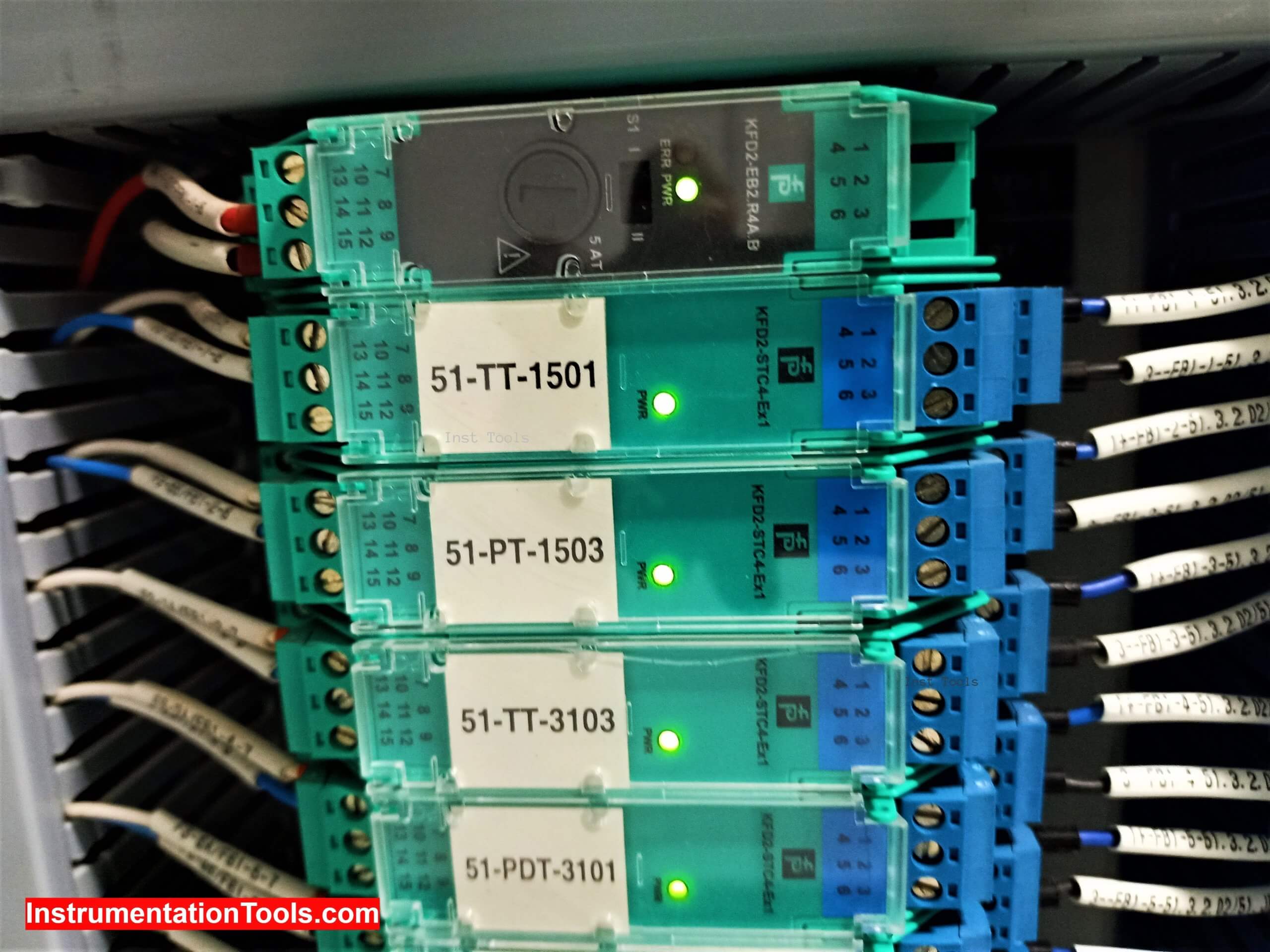
Energy limiting device or it is commonly known as a “Safety Barrier” is one of the major elements to achieve the Intrinsic Safety principle.
If you have experience dealing with instrumentation at Hazardous Area, you will find this topic familiar and if you do not have, I think this article would help you a lot.
Safety Barrier
So, here we are going to discuss what type of instruments should be installed at the EX (explosive) zones? In addition, how it should be installed with the Safe zone? To maintain safety at the highest level in DCS or PLC control systems.
What is meant by the EX (explosive) zone?
First, we have to understand some basic concepts and we will start with the most basic one, which is “the industrial zones are not the same they are categorized into different classes”.
It is clear for you to notice that the food industry needs are very different from oil industry requirements (in the Automation Technology point of view); every sector of the industry has different needs and considerations that must be noted.
So simply the EX zones are kind of areas that contain materials that have the ability to explosion whenever the explosion conditions are present, this material could be (Natural gas – Pure Hexane – Dust – Chemicals…).
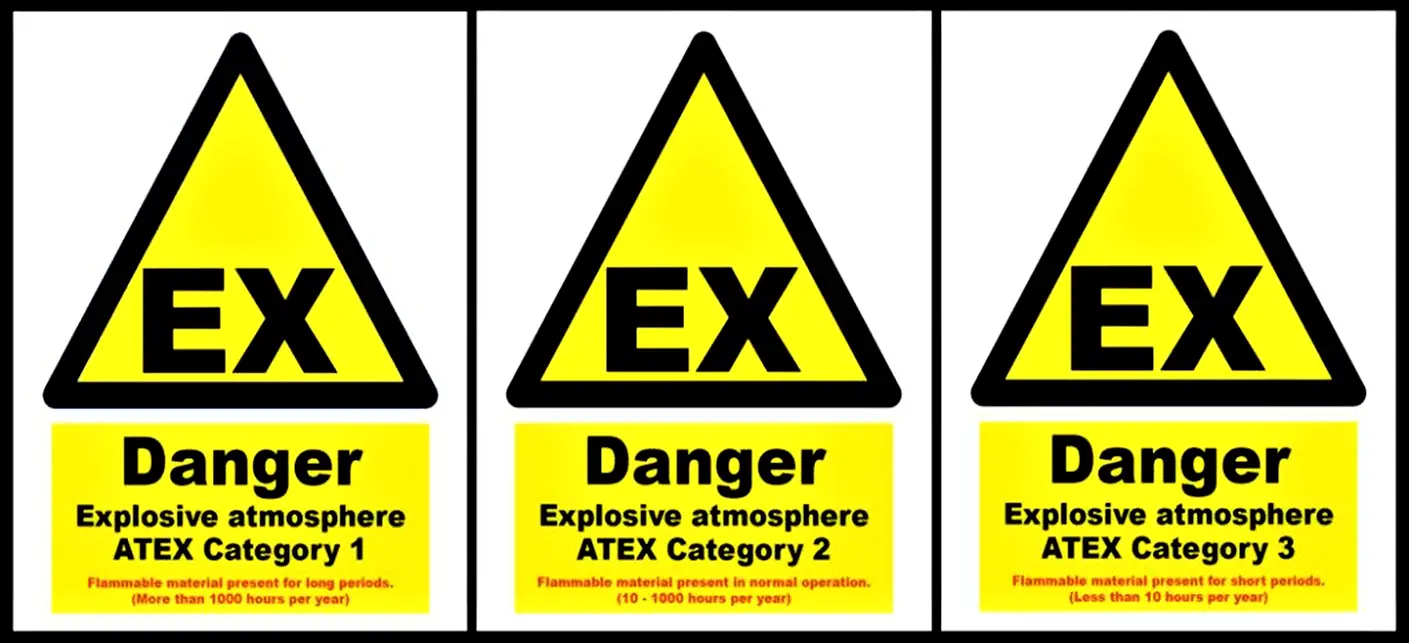
IEC/EN standards classified these zones into three levels; the level of risk of an explosion is based on the frequency and duration of the occurrence of an explosive atmosphere.
Why an Electric Equipment should be protected when it’s installed into an EX Zone?
That is really a critical question, but let us start from the Fire Triangle as all of us knows there are three reasons that should happen together to cause a Fire or Explosion:
- Oxygen
- Combustible Material
- Heat (ignition)
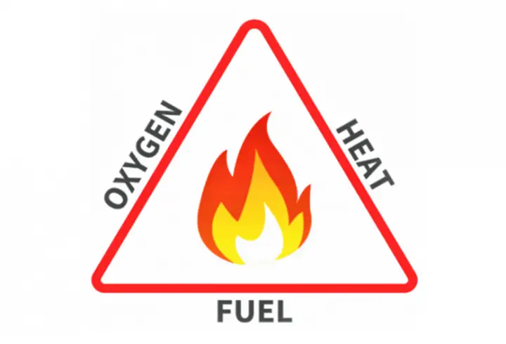
If you noticed that the only thing that is missed in the EX zones is the Ignition, and that is the role of electrical equipment.
If the electrical equipment cannot be installed safely (using Intrinsic Safety Principle), that may cause some spark due to any type of faults (short circuit – contacts changing) within the instrument, and by its role that would expose the field to a series danger.
Intrinsic Safety Principle
This expression could be defined, as one of the safest ways to ensure that an electrical device is installed in a hazardous location cannot result in a fire or explosion.
It is depending on limiting the amount of temperature and energy that is delivered to electric equipment.
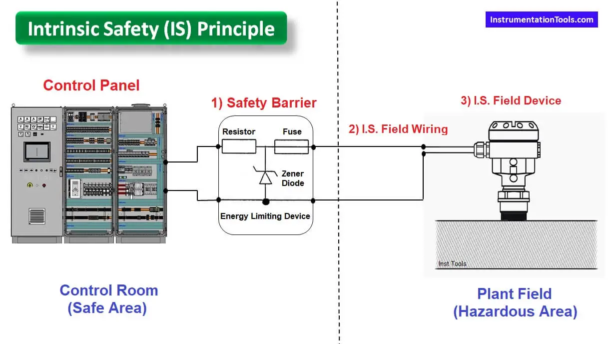
The intrinsic safety (I.S.) principle involves three major elements:
- Intrinsic safety field device.
- Safety Barrier.
- Intrinsic safety field wiring.
The idea behind the intrinsic safety principle is to limit the voltage, current, and power that is delivered to the field device to a certain safe limit.
So in the worst case and if any fault happened in the electric circuit (whatever at the safe or hazardous area), there will not be enough energy that can initiate the ignition that would make such an explosion.
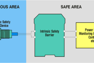
The idea behind a Safety Barrier
Under normal operations, the barrier is not needed as a safety device, the input voltage and current from the power source (at safe area) maybe go through the wiring to the field without any changes.
If a fault happens in the safe zone that causes a 220V go to the input terminals of the barrier, the output voltage will remain the same within its allowable maximum limits (such as 24V).
In addition, if that fault occurs at the field device’s side the safety barrier will maintain the operation voltage within its allowable limits.
Note
You have to ensure that the Safety Barrier & Field Instrument are compatible.
You could check that by reading the data of the safety barrier to get the allowable maximum voltage, current, and power (Vo – Io – Po) and compare them with the instrument allowable ranges (Vi – Ii – Pi).
For a good design, you have to ensure that:
Vo > Vi
Io > Ii
Po > Pi
How does a safety barrier physically work?
The barrier consists of a series resistor and a fuse plus a Zener diode that is grounded.
The series resistance limits the current to approximately to 100 mA from a 28 V supply when the dangerous terminals are shorted. The Zener diode operates in the 30 V region and the fuse has a power of around 30 mA.
The barrier thus ensures that either too much current or too much voltage will blow the fuse. This will keep any dangerous energy levels away from the hazardous area.
If you liked this article, then please subscribe to our YouTube Channel for PLC and SCADA video tutorials.
You can also follow us on Facebook and Twitter to receive daily updates.
Read Next:
- Security of SCADA System
- Free InTouch SCADA Training
- Earthing for PLC Control Panel
- Diagnostic Buffer SIEMENS PLC
- Tank Level Using PLC Program


Thank you for taking the time to post this.
Very excellent and informative. Thankful ????
Thankyou for valueable article