Industrial Process Plant Projects usually include many rotary or rotating equipment packages such as pumps, compressors, turbines, and so on, For their normal operations and reducing the friction effects, they need the oil lubrication unit. Sometimes such an oil unit will provide other functions (like Hydraulic Control) too.
Such an oil unit shall have some special requirements/specifications to provide or satisfy project needs and in this regard one of the environmental requirements is the oil temperature which usually will be compensated by Immersion Electric Heaters.
Lube Oil Console
For designing and supplying the Oil Unit of rotary equipment packages, Engineering Companies, and Manufacturers usually follow the API-614 standard. Such standard provides common requirements or specifications for such oil units which may be considered as basics of the design and supply of such items. Based on this standard, an Oil Unit is known as an Oil Console too, and the definition of such a unit is:
Console: A total system whose components and controls are packaged as a single unit on a continuous or joined baseplate.
NOTE 1: With a console, the purchaser is required only to make external connections.
NOTE 2: Rundown tanks and seal-oil tanks that are separately mounted, as well as other items such as instrumentation mounted on the equipment, are not part of the console.
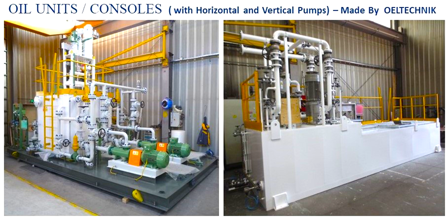
Figure 1: Two Samples of Oil Units / Consoles (Made By OELTECHNIK)
API-614 Standard for Lube Oil Consoles
As stated API-614 Standard with the title of “Lubrication, Shaft-sealing, and Oil-control Systems and Auxiliaries” usually is used for defining the requirements and specifications which shall be finalized between purchaser and manufacturer. At the beginning of this standard, we find that:
API 614 is not intended to inhibit a vendor from offering, or the purchaser from accepting, alternative equipment or engineering solutions for the individual application. This may be particularly appropriate where there is innovative or developing technology. Where an alternative is offered, the vendor should identify any variations from API 614 and provide details.
As it is clear from the mentioned phrase, such a standard is not mandatory and some items may be deviated based on purchaser and manufacturer agreements.
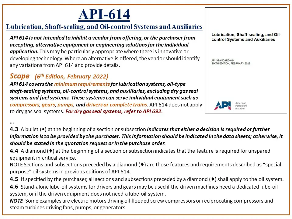
Figure-2: API-614 as a common usual standard for Lube Oil Consoles
Figure 2 shows the main scope of this standard and legend definitions for using this standard to specify the roles of purchasers in clarifying which sections of this standard are to be followed by the manufacturer. As an example, it declares that some project data shall be stated by the purchaser in a specified routine or document.
This Standard also provides the exact definition and meaning of technical terms relevant to Lube Oil Consoles (in order to make the same understanding for all).
Heating for Lube Oil Unit
Section 6.6.8 of API-614 Standard defines the requirements and specifications on “Heating” requirements of Lube Oil Consoles.
6.6.8.1 Heaters shall be provided if the minimum site temperature on the datasheet is less than the minimum oil start-up temperature required of the equipment being served.
Based on the standard, a Heating Function is required for the case of low oil temperature value at the start-up of the using Lube Oil Consoles (starting the pumps), although the Heating conditions shall be designed based on different other factors too (see Figure-3).
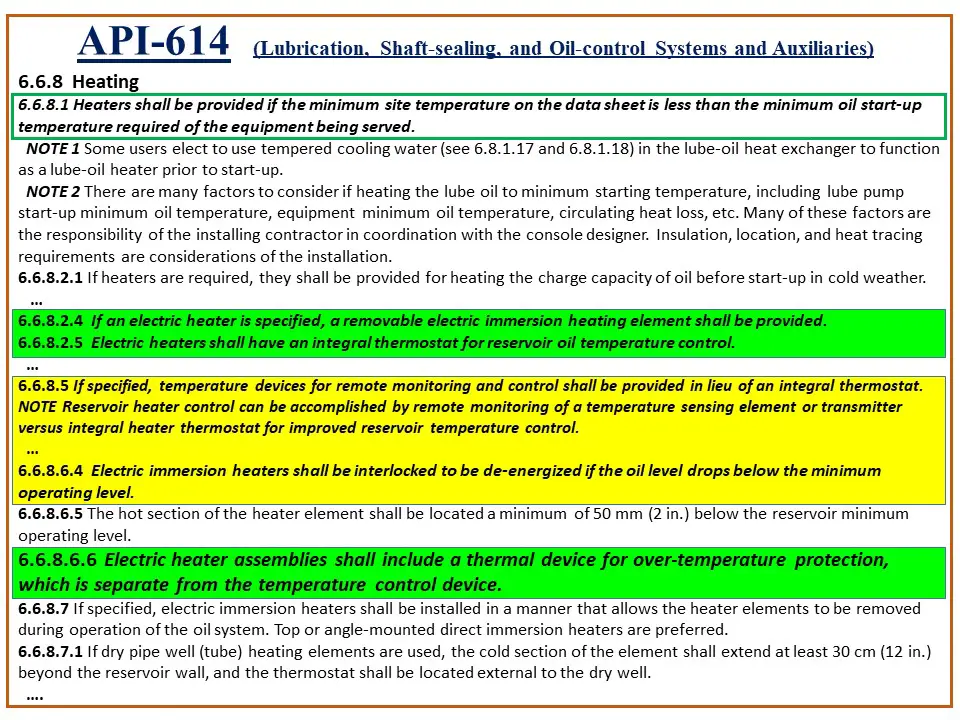
Figure 3: Heating Section of API-614 for defining Heating Conditions of Lube Oil Consoles (some extracted items)
The type of required Heater may be a Removable Steam Heater or a Removable Electric Immersion Heater. In any case, the size of the Heater shall be calculated and designed for rising the temperature of the mentioned oil capacity at console start-up during a defined specified time (considering environmental conditions).
It shall be mentioned that the API-614 specifies all requirements of Lube Oil Consoles including Structures, Pumps, Piping, Oil Level, and so on, but we have focused on the Heating Section of this Standard in this article.
Immersion Electrical Heaters
Usually, most designers and purchasers ask for Electrical Immersion Heaters for heating the oil in the Lube Oil Console, and hence from now we will use just Immersion Heaters instead of Electrical Immersion Heaters for simplicity.
Figure -4 shows some of the typical Immersion Heaters are available from different manufacturers.
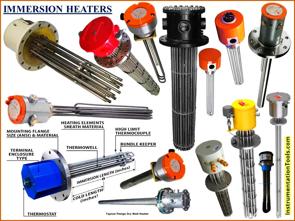
Figure 4: Some typical Immersion Heaters available by different manufacturers
Referring to Figure 3, the API-614 Standard specifies the removable facility of Immersion Heaters further to being equipped with two integral temperature measuring devices.
The Standard clearly specifies that one temperature measurement is used for the Control function while the other is used for Protection, and also strictly mentions that these two devices shall be separate from each other.
In fact the Control Temperature Measuring Device is used to make the Heater On and Off due to actual oil temperature, While the protection device is used to protect the Heater Failure due to Over-Temperature (malfunction).
So the protection device is conjunct to the Heating Elements Sheath Material (to measure Heater Elements Temperature), while the control device is floated in fluid (oil) to measure actual oil temperature.
API-614 has allowed using a Remote Temperature Monitoring Device (transmitter) instead of the integral thermostat, but the protection thermostat shall be an integral type. Please notice that since the target of the heating function is all lube oil capacity.
So using the remote device (having distance from Heater Elements) can provide a better function because the integral control device will monitor the oil temperature around the Heater Elements while the remote actual temperature may differ from the value of this device.
On the other hand, protection device cannot be installed in any other location than the Heater Element Sheath Material since it shall measure exactly the Heater Elements temperature.
Also as API-614 stated the Immersion Heaters shall be installed below minimum oil level and shall be interlocked with it.
6.6.8.6.4 Electric immersion heaters shall be interlocked to be de-energized if the oil level drops below the minimum operating level.
6.6.8.6.5 The hot section of the heater element shall be located a minimum of 50 mm (2 in.) below the reservoir’s minimum operating level.
It shall be noticed that if the oil console doesn’t have oil, then the heater element may be in contact with air, and so the control temperature device may not reach the off-point setting of the heater, which results in heater over (heat/) temperature. In this case, if two temperature devices merged as one (in opposite to API-614 Standard) then the heater will fail or will be damaged.
We can conclude that the level interlock is very important, especially for using remote temperature control/ monitoring cases. However, Level Interlock needed for pump start, and in some cases, designers may merge these two interlock functions by using just one level transmitter.
Activation of the protection temperature measurement device shows an abnormal case of Lube Oil Console operation (for heating function), and so such a device may need manual reset (after conditions checking by the operator).
Control Temperature Measuring Device does not require manual reset, since it shall be continuously switched on and off. Such a facility is considered by some heater manufacturers and to be considered carefully in relevant electrical circuit design (see the article “Immersion Heaters Wiring Circuits”).
Based on API-614 Standard, Heater Elements shall have a limit on producing heat:
6.6.8.6.1 Electric heaters shall not exceed a maximum watt density of 2.3 W/cm2 (15 W/in.2).
So for big Lube Oil Consoles, several sets of Heater Elements may be required, while for all circuits the above-mentioned interlocks shall be considered completely.
Different Configurations of Lube Oil Console
Figure 5 shows the Basic Oil Reservoir including Electrical Immersion Heaters which is used in different Lube Oil Console configurations in API-614 Standard.
Due to each project’s requirements, one of such configurations may be selected by the purchaser (/designer). Figure 5 just shows some of the different configurations shown in API-614 Standard (and there are some others that are not shown here).
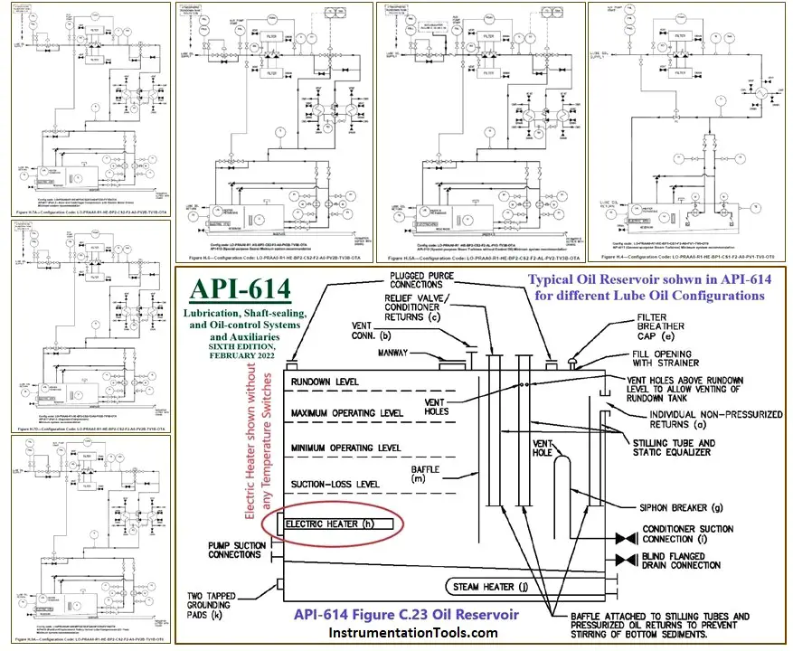
Figure-5: Some Configurations of Lube Oil Consoles in API-614 Standard
Ambiguity on Thermostat Signals Destinations
Referring to Figure-5 all Lube Oil console configurations use the basic Oil Reservoir shown considering Heating Function as explained in the standard. Although API-614 Standard explained the use of Immersion Heaters for Heating Functions, but unfortunately the destination of these signals are not so clear.
Since in different projects, different types of control and safety systems may be used for Lube Oil Console signals (Relays, DCS, ESD, PLC, Package Panel), sometimes vendors may have problems on showing the relevant signals due to the mentioned ambiguity.
It shall be mentioned that, the Heater Elements are driven by electrical power lines, and usually integral thermostat contacts (signals) are suitable for 220 VAC (or 110 VAC) too, while digital systems prefer to use 24 VDC directly or transferring mentioned AC voltages by using relays or suitable isolator circuits.
Furthermore, from site operation teams and safety points of view, it would be better for, heaters and auxiliary thermostats (integral or combined) to be in the scope of ELECTRICAL Team Operators’ responsibilities (otherwise I&C Team Operators may have problems for signal checking).
However wiring termination of Heater Thermostats may cause some discussions in different projects, but generally it would be better to consider these signals in power circuits or MCC (see “Immersion Heaters Wiring Circuits” article).
Vendor Document for Lube Oil System
Let us return to studying the vendors’ problems in showing the right signal destination by reviewing Figure-6 and Figure-7 which show two samples of realistic vendor documents.
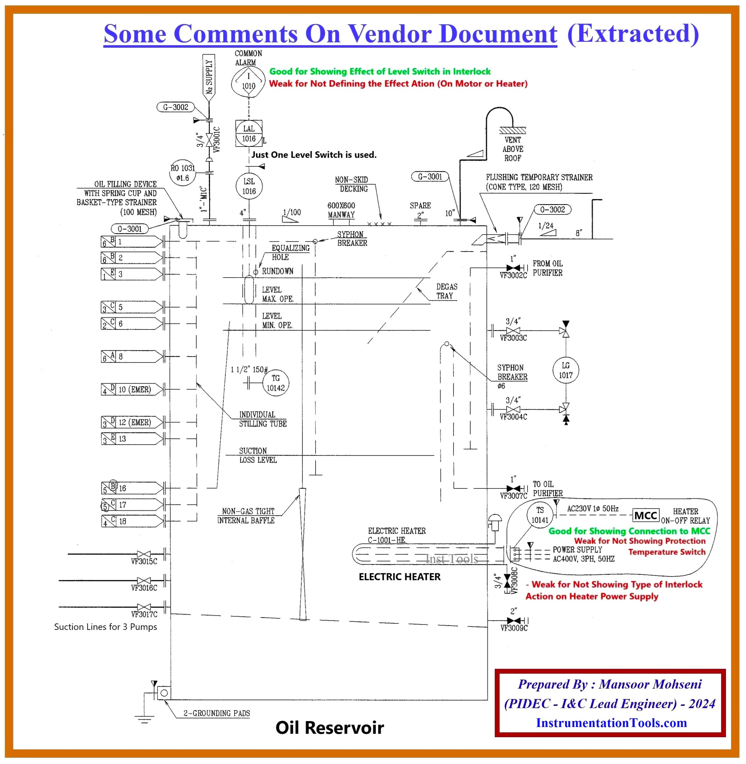
Figure 6: An example of comments on the Vendor Document for the Proposed Lube Oil Console
Figure 6 shows a Lube Oil Console which is equipped with one level switch and a heater with just one integral thermostat.
Since there is no Remote Temperature Measuring Device & heater interlock connection shown, and just only one thermostat tag number is specified, it will be supposed that this tag number will be the series connection of two integral thermostats, and otherwise it is contrary to API-614 Standard. For this document we can say at least :
It is good for: (In Figure-6)
- Showing the effect of the level switch on the interlock
- Showing connection of heater thermostats to MCC
- Showing clearly 3 phase heater with separate 230VAC Control Circuit
And it is weak for: (In Figure-6)
- Not defining the Level Switch action in the interlock (on the Pump Motor and/or Heater)
- Not showing the type of Interlock Action of the Heater Power Supply Circuit
- Not showing clearly Heater Protection Thermostat
Lube Oil Reservoir: Level and Temperature Transmitters
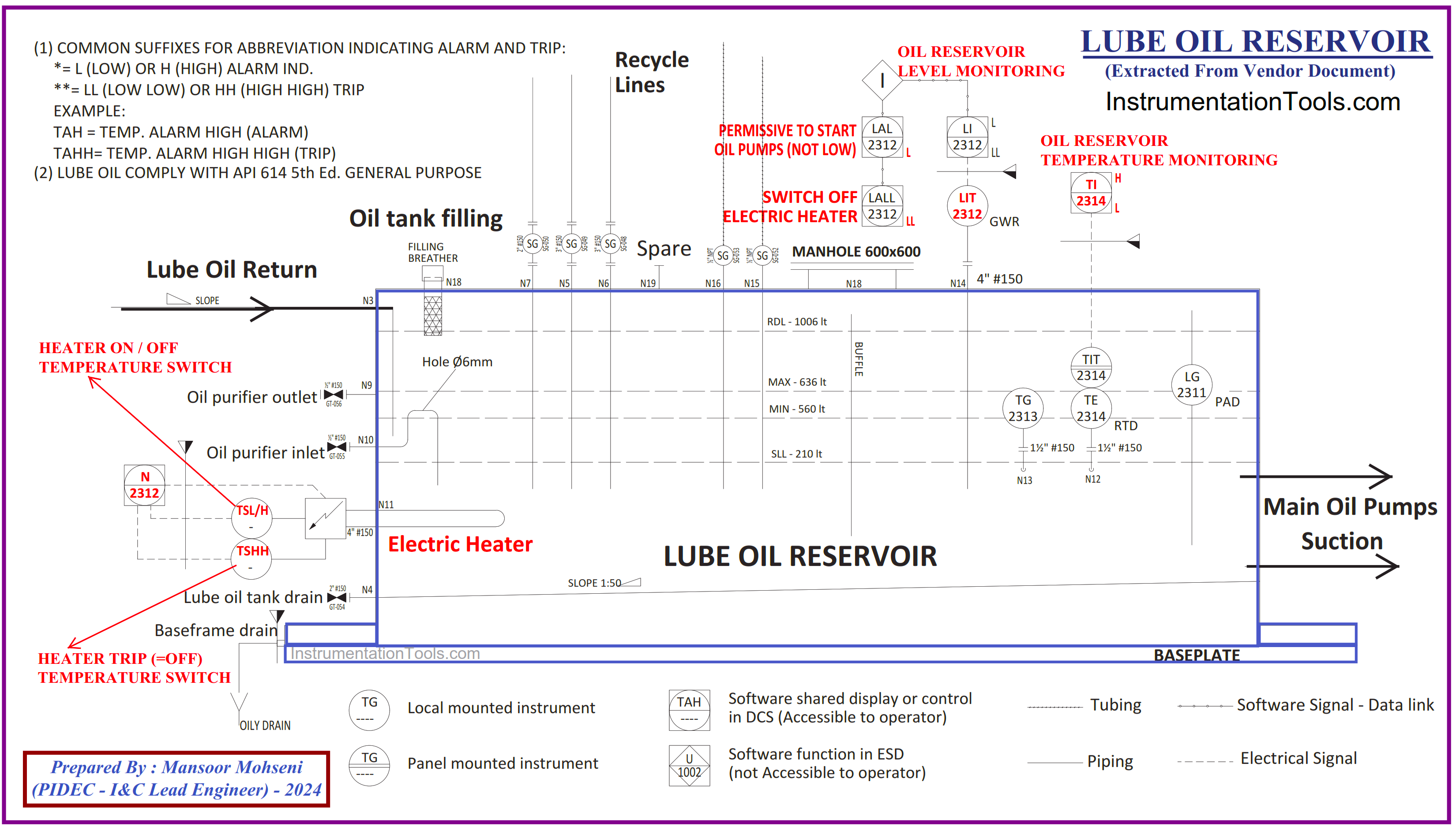
Figure-7: Another example of comments on the Vendor Document for the Proposed Lube Oil Console
Figure-7 shows a Lube Oil Console which is equipped with one level transmitter and one Remote Temperature Monitoring Transmitter further to a heater with two integral thermostats. Although this document seems to be good but we can say:
It is good for: (In Figure-7)
- Using one Level transmitter and showing two separate levels for different actions in Interlock (Permissive to Start Oil Pump & Switch Off Electric Heater)
- Showing Remote (Oil) Temperature Transmitter (with two levels H and L) on the opposite side of an installed heater on the Lube Oil Reservoir
- Showing two integral Temperature Switches combined with a Heater.
And it is weak for: (In Figure-7)
- Although it has a Remote Temperature Transmitter, there is no connection of this instrument to the Interlock shown.
- There is no clear indication of Level Interlock action on the Heater symbol shown.
- It seems that two heater thermostats will have action on the heater function but the wiring circuit of these thermostats is ambiguous (there is no MCC block shown for transferring signals).
- The type of the Electric Heater (3 Phase or Single Phase) and relevant power circuit is not clear.
Conclusion
API-614 Standard is a very good reference on Lube Oil Console for clarification of requirements and specifications between purchaser and vendor, but regarding Immersion Electric Heater Signals connection it is weak, and so purchaser and vendor shall have complete clarifications on this subject.
References:
- Immersion Heaters Wiring Circuits
- Package Systems Architecture Details
- Turbine-Compressor System Architecture