Inst ToolsInst ToolsInst Tools
  • Courses
  • Automation
    • PLC
    • Control System
    • Safety System
    • Communication
    • Fire & Gas System
  • Instrumentation
    • Design
    • Pressure
    • Temperature
    • Flow
    • Level
    • Vibration
    • Analyzer
    • Control Valve
    • Switch
    • Calibration
    • Erection & Commissioning
  • Interview
    • Instrumentation
    • Electrical
    • Electronics
    • Practical
  • Q&A
    • Instrumentation
    • Control System
    • Electrical
    • Electronics
    • Analog Electronics
    • Digital Electronics
    • Power Electronics
    • Microprocessor
  • Request
Search
  • Books
  • Software
  • Projects
  • Process
  • Tools
  • Basics
  • Formula
  • Power Plant
  • Root Cause Analysis
  • Electrical Basics
  • Animation
  • Standards
  • 4-20 mA Course
  • Siemens PLC Course
Reading: Reciprocating Compressors
Share
Notification Show More
Font ResizerAa
Inst ToolsInst Tools
Font ResizerAa
  • Courses
  • Design
  • PLC
  • Interview
  • Control System
Search
  • Courses
  • Automation
    • PLC
    • Control System
    • Safety System
    • Communication
    • Fire & Gas System
  • Instrumentation
    • Design
    • Pressure
    • Temperature
    • Flow
    • Level
    • Vibration
    • Analyzer
    • Control Valve
    • Switch
    • Calibration
    • Erection & Commissioning
  • Interview
    • Instrumentation
    • Electrical
    • Electronics
    • Practical
  • Q&A
    • Instrumentation
    • Control System
    • Electrical
    • Electronics
    • Analog Electronics
    • Digital Electronics
    • Power Electronics
    • Microprocessor
  • Request
Follow US
All rights reserved. Reproduction in whole or in part without written permission is prohibited.
Inst Tools > Blog > Process > Reciprocating Compressors

Reciprocating Compressors

Last updated: May 17, 2018 6:47 pm
Editorial Staff
Process
1 Comment
Share
3 Min Read
SHARE

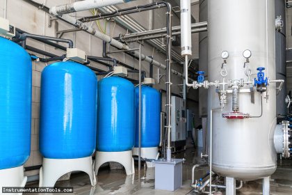
Air compressors of various designs are used widely in numerous applications. Compressed air has numerous uses throughout a facility including the operation of equipment and portable tools.

Three types of designs include

  1. Reciprocating compressor,
  2. Rotary compressor,
  3. Centrifugal air compressors.

Reciprocating Compressors

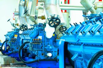
The reciprocating air compressor, illustrated in Figure 1, is the most common design employed today.

Reciprocating Air Compressors

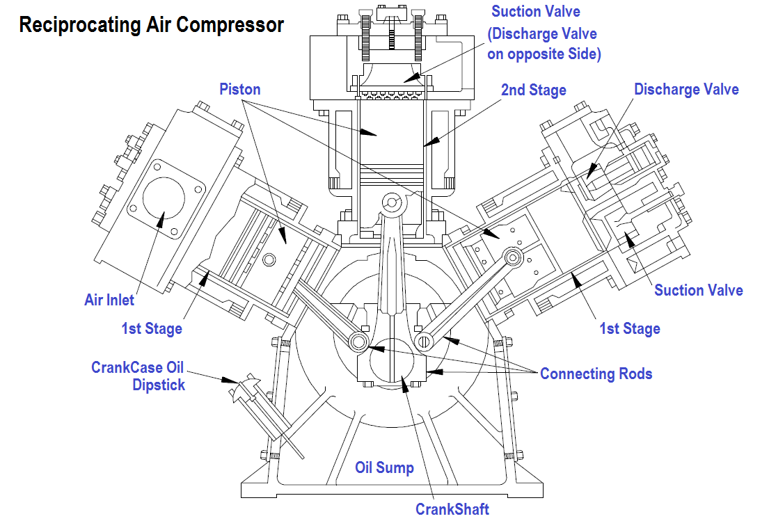
Figure 1 Reciprocating Air Compressor

The reciprocating compressor normally consists of the following elements.

  1. The compressing element, consisting of air cylinders, heads and pistons, and air inlet and discharge valves.
  2. A system of connecting rods, piston rods, cross-heads, and a crankshaft and flywheel for transmitting the power developed by the driving unit to the air cylinder piston.
  3. A self-contained lubricating system for bearings, gears, and cylinder walls,  including a reservoir or sump for the lubricating oil, and a pump, or other means of delivering oil to the various parts. On some compressors a separate force-fed lubricator is installed to supply oil to the compressor cylinders.
  4. A regulation or control system designed to maintain the pressure in the discharge line and air receiver (storage tank) within a predetermined range of pressure.
  5. An unloading system, which operates in conjunction with the regulator, to reduce or eliminate the load put on the prime mover when starting the unit.

A section of a typical reciprocating single-stage, single-acting compressor cylinder is shown in Figure 2. Inlet and discharge valves are located in the clearance space and connected through ports in the cylinder head to the inlet and discharge connections.

Single-Acting Air Compressor Cylinder

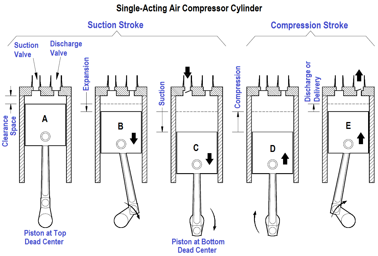
Figure 2 : Single-Acting Air Compressor Cylinder

During the suction stroke the compressor piston starts its downward stroke and the air under pressure in the clearance space rapidly expands until the pressure falls below that on the opposite side of the inlet valve (Figures 2B and 2C). This difference in pressure causes the inlet valve to open into the cylinder until the piston reaches the bottom of its stroke (Figure 2C).

During the compression stroke the piston starts upward, compression begins, and at point D has reached the same pressure as the compressor intake. The spring-loaded inlet valve then closes. As the piston continues upward, air is compressed until the pressure in the cylinder becomes great enough to open the discharge valve against the pressure of the valve springs and the pressure of the discharge line (Figure 2E). From this point, to the end of the stroke (Figures 2E and 2A), the air compressed within the cylinder is discharged at practically constant pressure.

Don't Miss Our Updates
Be the first to get exclusive content straight to your email.
We promise not to spam you. You can unsubscribe at any time.
Invalid email address
You've successfully subscribed !

Continue Reading

Pressurizer
Refrigeration Compressor Turbine Not-tripping when needed Trip
Difference Between Single-stage and Multi-stage Compressor
Backwashing
Questions and Answers on Gas
Filters in Compressors
Share This Article
Facebook Whatsapp Whatsapp LinkedIn Copy Link
Share
1 Comment
  • christian mshila says:
    May 6, 2024 at 9:22 pm

    Hi, was reading this article on compressors.
    am currently writing a section of compressed air as a co author in a book. can i use your figures to illustrate the types of compressors.

    Reply

Leave a Reply Cancel reply

Your email address will not be published. Required fields are marked *

Stay Connected

128.3kFollowersLike
69.1kFollowersFollow
210kSubscribersSubscribe
38kFollowersFollow

Categories

Explore More

Desuperheater Design
Impulse Steam Trap
Process Control High Level Alarm Fault Analysis
Introduction to Wastewater Treatment Works and Pumping Station
Demineralizers
Membrane Bioreactor in Water Treatment – MBR Process
Process Engineering Roles & Responsibilities – Design Company
Components of Water Treatment Plant

Keep Learning

Heat Exchanger Root Cause Analysis

Heat Exchanger Root Cause Analysis (RCA)

Water Treatment Plant

Difference Between ETP, STP, and WTP – Treatment Plants for Water

interview-questions-and-answers-on-natural-gas

Oil and Gas Interview Questions Answers

Practical Process Control System Questions

Process Control Loop Testing

Multi-Cartridge Filter

Cartridge Filters

Hazards of Compressed Air

Hazards of Compressed Air

Process Control Fundamentals

Process Control Fundamentals

Water Treatment Industry

Water Softening Systems in Water Treatment Industry

Learn More

Multiplexing

Introduction to Digital Systems

PLC Load Memory

What is Resources Tab in the Siemens PLC?

Loop Current Step Response (LCSR) Test for RTD

Response Time Test of RTD and Thermocouple

Rotary Liquid Seal Ring Air Compressor

Rotary Compressors

Radiation Exposure Converter

Free Online Radiation Exposure Calculating Platform

Troubleshooting a Biased Transistor

Troubleshooting a Biased Transistor

Bubbler Level Measurement System

Bubbler Level Sensor

Overview of Proximity Switches

Menu

  • About
  • Privacy Policy
  • Copyright

Quick Links

  • Learn PLC
  • Helping Hand
  • Part Time Job

YouTube Subscribe

Follow US
All rights reserved. Reproduction in whole or in part without written permission is prohibited.
Welcome Back!

Sign in to your account

Username or Email Address
Password

Lost your password?