Lube Oil Consoles of rotary equipment packages (like Pumps, Compressors, Turbines, .…) in Industrial Process plants are usually equipped with Immersion Electrical Heaters.
Immersion Electrical Heaters
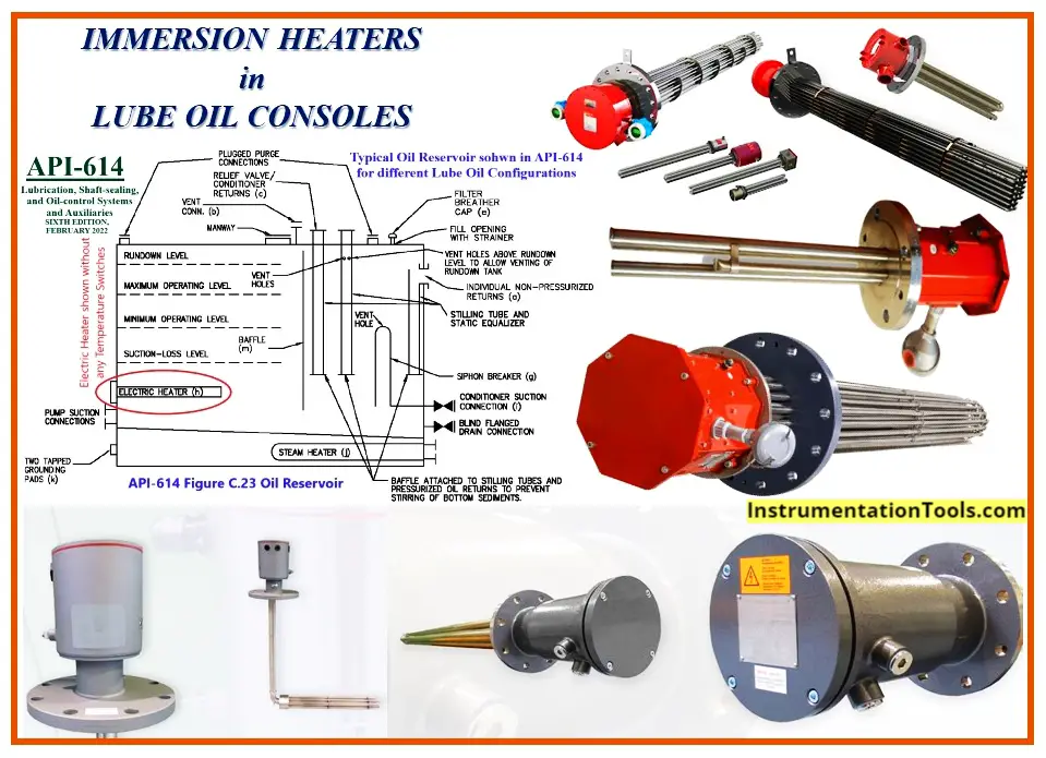
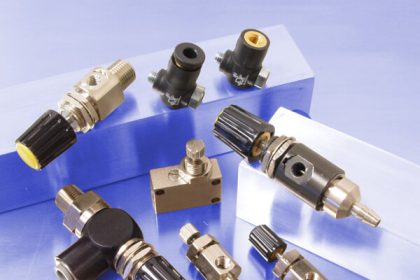
Figure 1.1: Some Immersion Electric Heaters Used in Lube Oil Consoles.
API-614 Standard that defines requirements and specifications of Lube Oil Consoles (in the Heating Section) declares that in the case of using an Immersion Electric Heater, it shall be used with two separate Temperature Measuring Devices (See reference article).
One of them is used as input for the ON-OFF Control Function and the other one has a Heater Over-Temperature Protection role. The Protection Thermostat shall be an integral part of the heater to measure the Heater Element Sheath Material Temperature.
Temperature Control Device may be an integral part of the heater or may be installed on the Lube Oil Reservoir as a Remote Temperature Monitoring Device.
In any case, the Temperature Control Device is used to measure Oil Temperature and in the case of low temperature at the Lube Oil Console Start-up, the Heater will be switched on to increase the oil temperature.
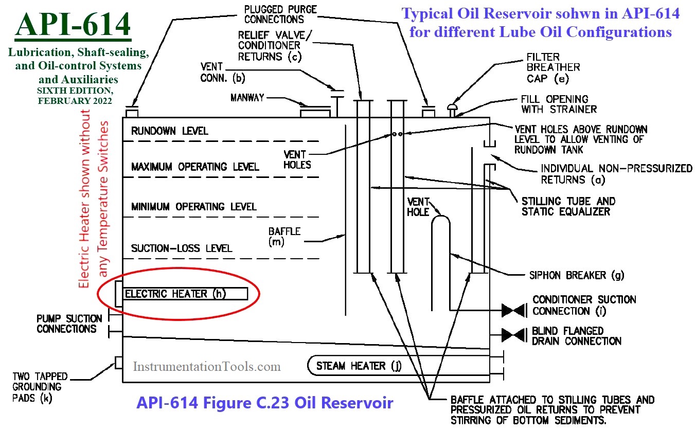
Figure 1.2: Oil Reservoir
The Oil Level in the Lube Oil Reservoir is another parameter to be interlocked for the heater switch on. In the case of low-level oil in the Lube Oil Reservoir, the heater circuit is not allowed to switch on the heater.
In order to satisfy API-614 requirements, manufacturer of Immersion Electric Heaters usually made their products with two integral thermostats, which one of them (Temperature Control) is Auto Reset, while the other one (Temperature Protection) needs Manual Reset.
Manufacturers also provide their products in two formats for use in single-phase or 3 phases electric circuits. Figure 2 shows one of the typical Immersion Electric Heaters that have mentioned facilities.
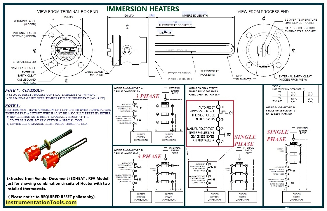
Figure 2: One of Typical Immersion Electric Heaters with 2 thermostats
Wiring Problems of Immersion Electric Heaters
Although API-614 Standard explained the use of an Immersion Heater for Heating Functions, unfortunately the destination of thermostat signals is not so clear. In different projects, different types of control and safety systems may be used for Lube Oil Console signals (Relays, DCS, ESD, PLC, Package Panel).
Sometimes vendors may have problems showing the relevant signals due to the mentioned ambiguity, and so the purchaser and vendor shall have complete clarifications on this subject (See reference article).
Usually, the contacts of thermostats which are integral parts of Immersion Electric Heaters are suitable for use in 220 VAC (or 110 VAC) circuits while digital systems prefer to use 24VDC signals.
Also when two thermostats are an integral part of heaters, the terminal connections of switches are very close to the power terminal connection of heaters (see Figure-3).
Someone may say that since thermostat contacts are free potential ones, they may be used in low voltage DC circuits too (if the contact conductivity is good) and in this regard, they may install an external isolation divider in the heater terminal enclosure, but since the space is usually tight, still they will have a problem.
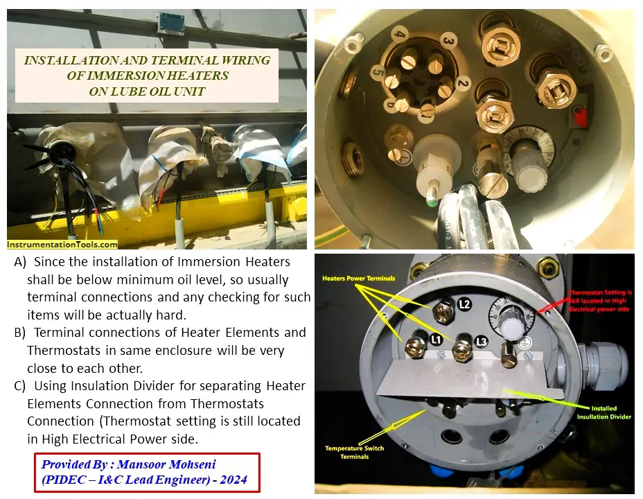
Figure 3: Immersion Electric Heater Wiring Problems
As Figure 3 shows, even by installing the isolation divider, the location of the thermostat setting (or maybe Manual Reset) still has access problems for I&C Site Operators. It shall be noted that during the operation and maintenance phase of Process Plants, due to maintenance routines, the thermostat switches shall be checked, and also in the case of Over Heat Temperature activated, it shall be manually reset.
For such activities, the heater power terminal enclosure shall be opened while from the safety point of view, it is not safe. Also, heater power terminals are in the scope of ELECTRICAL Site Operators, and opening the enclosure shall have their permit (or by presence of their specialists).
If two heater thermostats are located in separate boxes behind the power terminal box, since the temperature elements (sensors) still are installed in near (or in contact) to heater elements, still it would be better to consider their switch contacts in the power control circuit.
Also as Figure 3 shows, since the installation of Immersion Heaters shall be below minimum oil level, so usually terminal connections and any checking for such items will be actually hard (contact checking would be better checked from isolation relays).
Due to the mentioned problems, and also opening the heater terminal box shall be done by exact care of ELECTRICAL Site Operators, it would be better to consider any actions on Immersion Electric Heaters to be done by this team (adding I&C Site Operators for such activities may rise some responsibility problems).
On the other hand, the best solution for the Immersion Electric heater thermostat connection is to consider them in the Power Control Circuit (MCC) of the Heater (as we will see in the following).
Remote Temperature Monitoring Vs. Integral Temperature Control – Line Heaters
The Heater On-Off function shall be done by an Oil Temperature Measuring Device, so if it is installed in a position to sense the actual oil temperature the total performance would be better.
On the other hand, for using Immersion Electric Heaters in Lube Oil Reservoirs (especially for big ones) the best performance can be achieved by a Remote Monitoring Temperature Device.
Using a Temperature Control Device as an integral part of Electric Heaters may have an advantage for limited space cases like line heaters as shown in Figure 4.
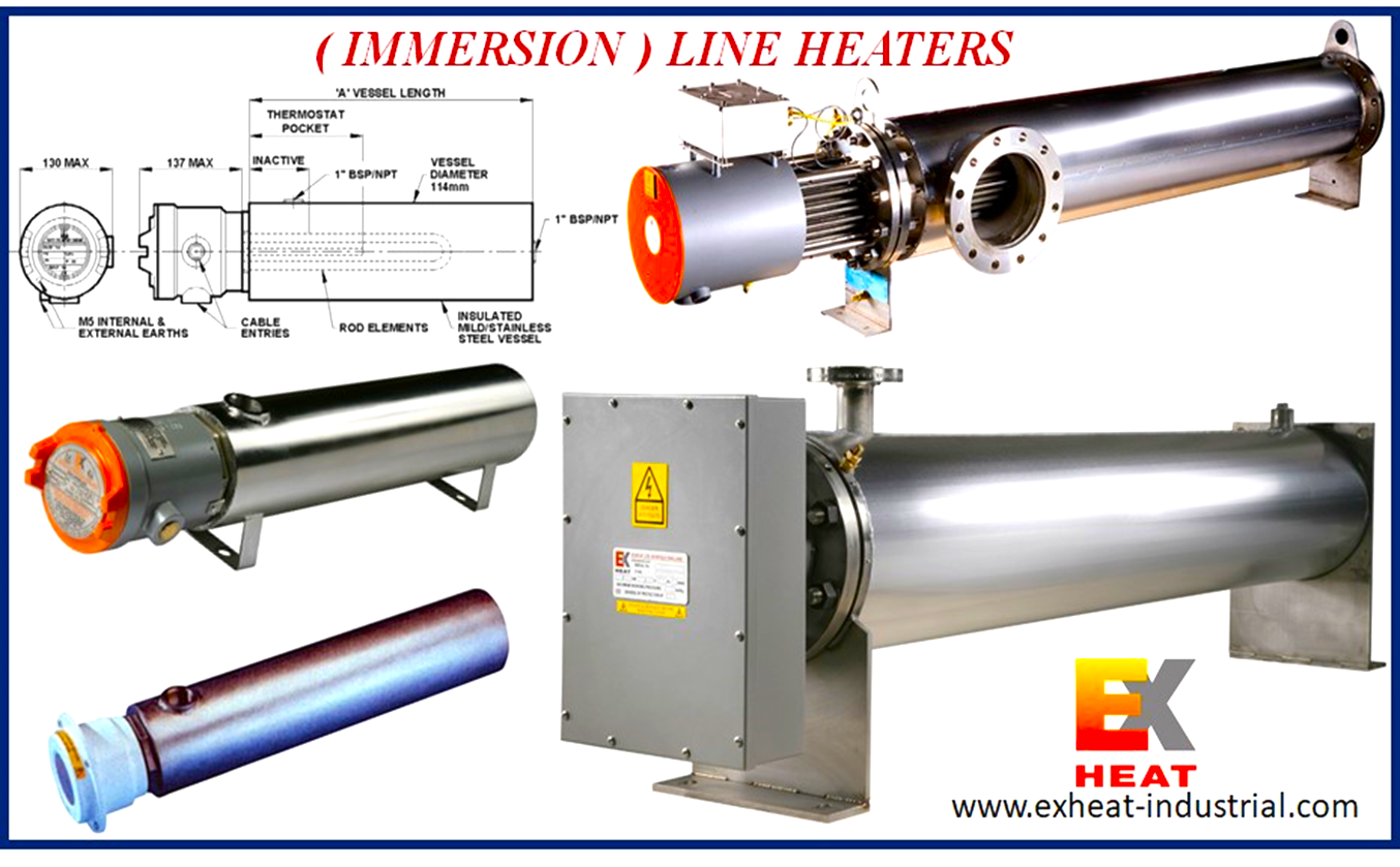
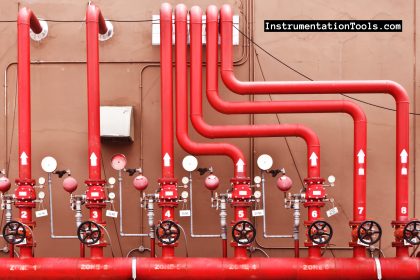
Figure 4: Using Immersion Electric Heaters as Line Heaters
Wiring of Immersion Electric Heaters in MCC
As we have concluded the good suggestion for the wiring connection of Immersion Electric Heater Thermostats is using their contacts in the Power Control circuit or MCC.
Due to different needs for required monitoring signals (in different projects and design needs) we can use such switch contacts in different configurations.
Also due to the type of electric heaters as single-phase or 3-phase, we may select a suitable circuit for MCC.
Single Phase Immersion Electrical Heaters
3 different cases for using thermostat contacts in Single-Phase Heater MCC (Basic Circuits) are shown in Figure 5.
We can review the considered configurations in 3 cases as below:
Single-phase Heater Case-1:
- Both Thermostat Contacts are in series with the Electric Heater Power Loop (feeder) directly.
- The heater will be switched on and off just based on Integral Thermostat Contact.
- The heater will be protected by Integral Thermostat Contact.
- The heater can be switched off by the Local Control Station too.
- Digital System has Heater Enable facility by series connection of two contacts (One Trip Signal and the other Interlock output may be from Level Measuring Device)
- The Fault Feedback Signal transferred to the Digital System shows MCC Circuit faults.
- The Heater On feedback signal to the Digital System is showing just the power transfer to the Electric Heater and is not the real situation of the Heater in action.
- There is no any feedback lamp on the Local Control Station to show the Heater in action.
- There is no any monitoring signal for operators to know the Manual Reset is required in both the Digital System and in the Local Control Station.
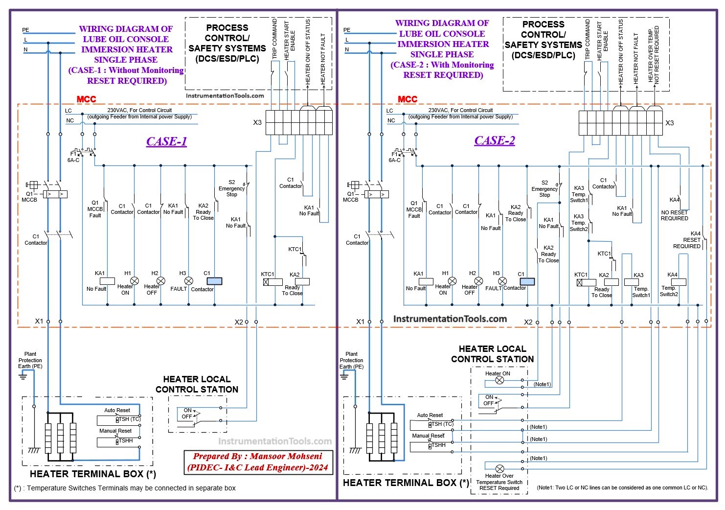
Figure-5.1: Three Different Cases of Using Thermostat Contacts in Single Phase MCC
Single-phase Heater Case-2:
- Both Thermostat Contacts are in series with an Electric Heater Power Control Circuit and the Heater will have a separate feeder.
- The heater will be switched on and off based on Integral Thermostat Contact or Digital System Outputs.
- The heater will be protected by Integral Thermostat Contact.
- The heater can be switched off by the Local Control Station too.
- Digital System has a Heater Enable facility by series connection of two contacts (One Trip Signal and the other Interlock output may be from Level Measuring Device).
- The Fault Feedback Signal transferred to the Digital System shows MCC Circuit faults.
- The Heater On feedback signal to the Digital System shows the real situation of whether the Heater is in action or not.
- The Heater On feedback signal to the Local Control Station shows the real situation of the Heater is in action or not.
- There is a monitoring signal for operators to know as Manual Reset. It is required in both the Digital System and in Local Control Station.
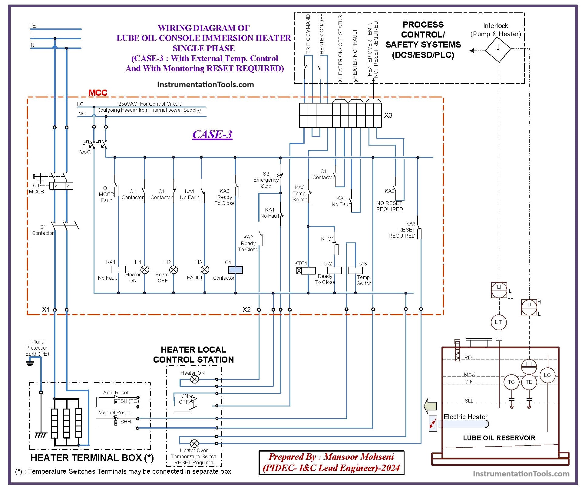
Figure-5.2: Single-Phase Immersion Heater
Single-phase Heater Case-3:
- Over-Heat Protection Thermostat Contact are in series with Electric Heater Power Control Circuit and Heater will have separate feeder, while Integral Heater Control Thermostat is not used (or may be used as redundant control!).
- Heater will be switched on and off based on Digital System Outputs.
- Heater will be protected by Integral Thermostat Contact.
- Heater can be switched off by Local Control Station too.
- Digital System has Heater Enable and switch on and off facilities by series connection of two contacts (One Trip Signal and the other Interlock output from Level Measuring Device and also Remote Monitoring Temperature Measuring Device).
- The Fault Feedback Signal transferred to Digital System shows MCC Circuit faults.
- The Heater On feedback signal to Digital System is showing the real situation of Heater in action or not.
- The Heater On feedback signal to Local Control Station is showing the real situation of Heater in action or not.
- There is a monitoring signal for operators to know Manual Reset Is Required in both Digital System and in Local Control Station.
Three-Phase Immersion Electrical Heaters
3 different cases for using thermostat contacts in 3-Phase Heater MCC (Basic Circuits) are shown in Figure-6.
3-phase Heater Case-1:
- Both Thermostat Contacts are in series with Electric Heater Power Control Circuit and Heater will have separate feeder.
- The heater will be switched on and off based on Integral Thermostat Contact or by Digital System Outputs.
- The heater will be protected by Integral Thermostat Contact.
- The heater can be switched off by the Local Control Station too.
- The Digital System has a Heater Enable and switch on and off facilities by series connection of two contacts (One Trip Signal and the other Interlock output may be from the Level Measuring Device).
- The Fault Feedback Signal transferred to Digital System shows MCC Circuit faults.
- The Heater On feedback signal to Digital System is showing the real situation of Heater in action or not.
- There is a feedback lamp on Local Control Station for showing Heater in action or not.
- There is no any monitoring signal for operators to know Manual Reset Is Required in both Digital System and in Local Control Station.
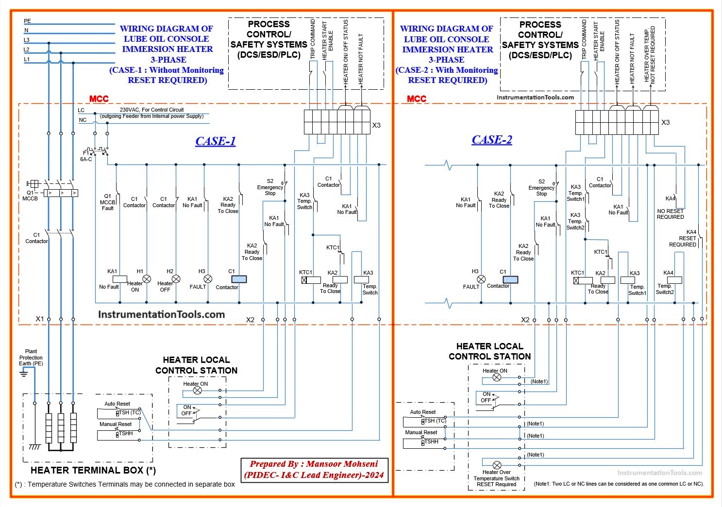
Figure-6.1: Three Different Cases of Using Thermostat Contacts in 3-Phase MCC
3-phase Heater Case-2:
- Both Thermostat Contacts are transferred separately and in series with Electric Heater Power Control Circuit and Heater will have separate feeder.
- Heater will be switched on and off based on Integral Thermostat Contact or Digital System Outputs.
- The heater will be protected by Integral Thermostat Contact.
- The heater can be switched off by the Local Control Station too.
- The Digital System has Heater Enable and switch on and off facilities by series connection of two contacts (One Trip Signal and the other Interlock output may be from Level Measuring Device).
- The Fault Feedback Signal transferred to Digital System shows MCC Circuit faults.
- The Heater On feedback signal to Digital System is showing the real situation of Heater is in action or not.
- The Heater On feedback signal to Local Control Station shows the real situation of Heater is in action or not.
- There is a monitoring signal for operators to know Manual Reset Is Required in both Digital System and in Local Control Station.
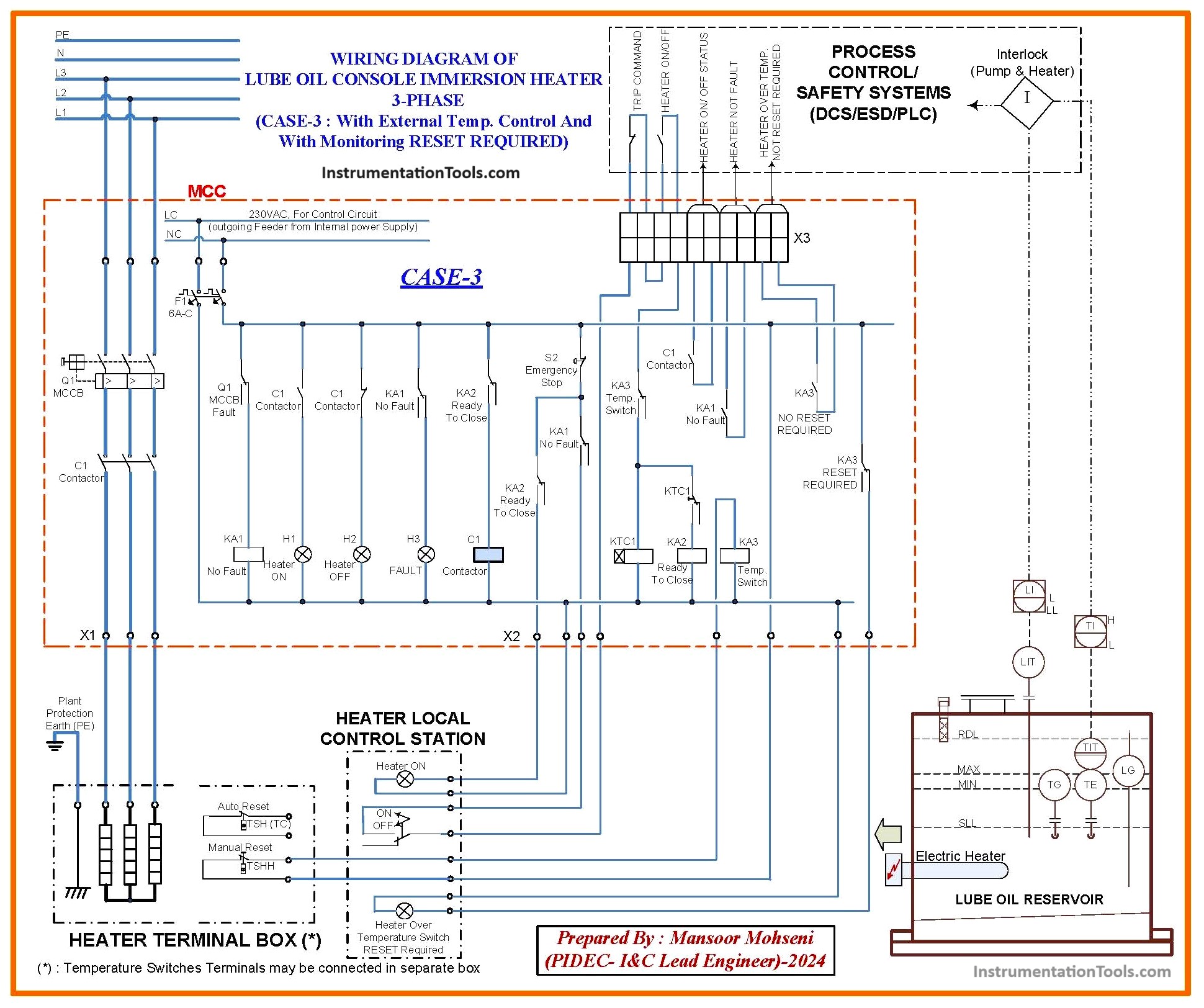
Figure-6.2: Three-Phase Immersion Heater
3-phase Heater Case-3:
- Over-heat protection Thermostat Contact is in series with the Electric Heater Power Control Circuit and the Heater will have a separate feeder, while the Integral Heater Control Thermostat is not used (or may be used as redundant control!).
- The heater will be switched on and off based on Digital System Outputs.
- The heater will be protected by Integral Thermostat Contact.
- The heater can be switched off by the Local Control Station too.
- The Digital System has a Heater enable and switches on and off facilities by a series connection of two contacts (One Trip Signal and the other Interlock output from the Level Measuring Device and also the Remote Monitoring Temperature Measuring Device).
- The Fault Feedback Signal transferred to the Digital System shows MCC Circuit faults.
- The Heater On feedback signal to the Digital System shows the real situation of the Heater is in action or not.
- The Heater On feedback signal to Local Control Station is showing the real situation of Heater is in action or not.
- There is a monitoring signal for operators to know Manual Reset Is Required in both Digital System and in Local Control Station.
References:
- Immersion Heaters in Lube Oil Consoles
- Package Systems Architecture Details
- Turbine-Compressor System Architecture