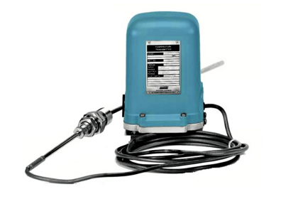
The thermowell is the industrial housing for temperature elements like RTD or thermocouple or temperature gauges. Thermowell is directly exposed to process fluid/media. Inside the thermowell, element/gauge is installed.
Thermowell transfers the heat to the temperature element. Depending upon the element type, the fluid temperature can be known. So Thermowell protects the temperature element against harsh conditions and process fluid. It enables removal of the temperature element for replacement, repair, or testing without affecting the process system.
Generally, thermowells are provided with all-temperature Elements like RTD or Thermocouple or temperature gauge. A few exceptions would be bearing RTD, skin type thermocouple, air duct thermometer, etc where thermowell is not applicable / required.
When the thermowell assembly is inserted into the pipe, it is subjected to vibration. This vibration is caused by vortices to be generated alternately on either side of the thermowell. The vortices cause the thermowell assembly to vibrate and can result in premature failure. That is why the need for sizing and designing the thermowell according to international standards.
Thermowells shall be designed and manufactured in accordance with ASME PTC 19.3 TW – 2016 code based on operating and maximum values of temperature, pressure, medium, and fluid velocity. A properly selected thermowell will protect the temperature element from damage due to vibration.
This standard applies to thermowells machined from bar stock and includes those welded to or threaded into a flange as well as those welded into a process vessel or pipe with or without a weld adaptor. Thermowells manufactured from pipes are outside the scope of this standard.
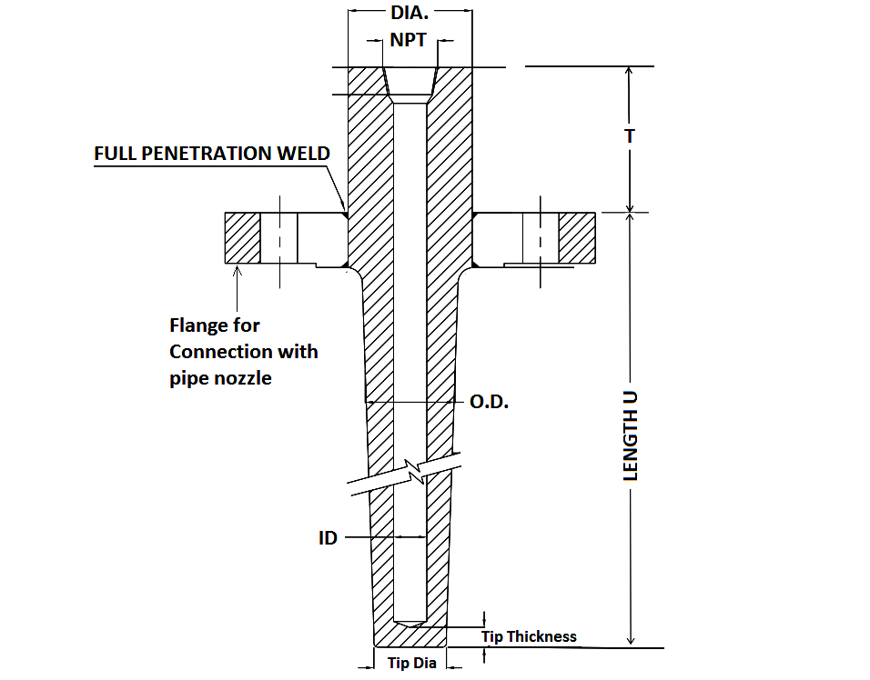
The Flanged and welded design is shown below. It is always better to provide a sketch of thermowell with the required specification when doing inquiry. The sketch should include tip diameter, tip thickness, well internal diameter, tapered length, unsupported diameter, instrument connection detail, etc.
Thermowell General Specifications
It should cover the following minimum aspects.
TW should be one-piece SS316 as a minimum (depending upon service different material can be used). Sometimes, welding of dissimilar metal of flange and thermowell is not allowed. Sometimes, specific requirement calls for hardening of thermowell. Hardfacing thickness and hard facing on immersion length are important.
Lined / sleeve thermowell is an economical solution for chemically aggressive fluids. The base material can be SS316. However, the lining can be selected as Hastelloy-C, Nickel, Titanium, Tantalum, Silver depending upon fluid. This will provide strength from stainless steel & corrosion resistance from the lining.
Special care shall be taken when selecting the correct Thermowell design and material for high-temperature application. Vendor shall be consulted for temperature measurement like > 900o C
Sometimes “Protection Tubes” instead of thermowells are used to protect thermocouples. These protection tubes are usually fabricated of ceramic materials and they are installed in high-temperature flue gas and duct applications. Protection tubes are also available made of Inconel and with their ends open in order to improve the speed of response and heat transfer.
TW should have a tapered design and shall be drilled from solid bar stock.
Instrument connection for thermowell should be ½” NPT (F) – that is for temperature element connection inside the thermowell.
The bore size of the thermowell should be suitable for the respective temperature element OD. e.g. suitable for 6 mm OD sheathed RTD.
Flanged thermowells should normally be selected. Welding thermowells should only be installed where high velocity and density of the fluid, the bending loads are too high for flanged thermowells.
Thermowell is preferred to install at 90o from pipe axis. However, it is allowed to install on 45o from pipe axis or on pipe elbow.
When thermowell is installed near to DP type flow transmitter (Orifice element, venturi or pitot tube) or vortex type flowmeter, sufficient distance should be maintained to avoid flow measurement error.
Dye penetration testing for weld joints, hydro testing, bore concentricity should be performed for TW. Certification from relevant authorities, as applicable, should be considered.
General Guideline for Thermowell Sizing and Length
It is important to know the difference between insertion length and immersion length.
Thermowell Immersion Length
The immersion length of a thermowell is the distance between the tip of the thermowell and the point of immersion in the medium that is being measured. The standard symbol for the immersion length of a thermowell is “R”.
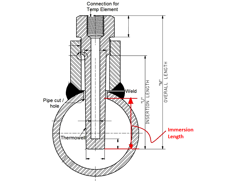
Thermowell Insertion Length
The insertion length of a thermowell is the distance between the tip of a thermowell and (but not including) the external threads of other means of attachment to a vessel. The standard symbol for the insertion length of a thermowell is “U”.
The insertion length “U” is always equal to or larger than the immersion length “R” of a thermowell.
API RP 551: TW installed perpendicular to the pipe wall should have a minimum immersion length of 2 inches.
A general thumb rule is to use an immersion length equaling a minimum of 10 times the diameter of the thermowell.
Some client has their specific requirement or standard requirement for insertion length based on pipe size. e.g. DEP 31.38.01.11-Gen.
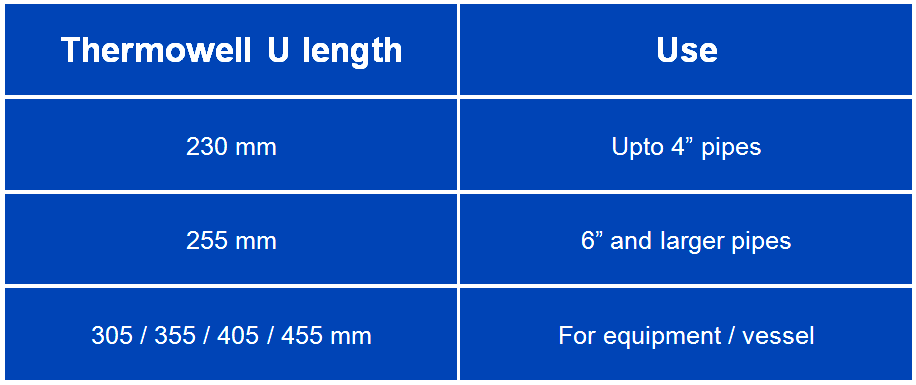
Some client specifies thermowell tip should be in between 1/3 and 2/3 of pipe ID or ½ of vessel ID to get a better temperature accuracy.
Thermowell Length
Overall thermowell length for flanged type design can be worked out with the following details:
- Nozzle neck length
- Insulation thickness
- Minimum insertion length requirement
In the case of thermowell wake frequency calculation fails according to PTC 19.3, the following can be exercised.
- Increasing Root & Tip diameter within a specified limit of standard. However, it may result in a delay in response time.
- U length reduction (however, maintain minimum requirement set by API RP 551 and/or contract specification)
- Reduce nozzle neck length (e.g. 200 mm to 150 mm)
- Consideration of strake designed thermowell (e.g. HelicalWell / ScrutonWell / Twisted square thermowell )
- Increase the size of the nozzle (e.g. 1.5” to 2” flanged)
Author: Jatin Katrodiya
Read Next:
- I&C General Specifications
- Temperature Sensors Questions
- Inter Discipline Check (IDC)
- Transmitter Detailed Specification
- Transmitter Calibration Frequency


It’s nice and very helpful.Please provide manual calculation formulae for all measurements instead of your calculator…THANK YOU…
Great post
im looking for a part number were I can purchase the graphite that goes inside the TW
Hi…6″ and larger pipe sizes we are limiting the insertion length to 255 mm.
i have a query, what if the pipe is not full and the thermowell is not touching the fluid in larger diameter pipes.
Will there be proper measurement or pipe needs to be always full?
How much thermowell size required in 1″ inch pipe line ?