10-years persisting Boiler Feed Water Heater Shell Flange leaks and causes ammonia plant trips. This root cause analysis (RCA) eliminated the problems.
| Article Type: | Root Cause Analysis (RCA) |
| Category: | Mechanical |
| Equipment Type: | Pipelines and Miscellaneous Problems |
| Author: | S. Raghava Chari |
Note: This root cause analysis (RCA) is from real-time scenarios that happened in industries during the tenure of two or three decades ago. These articles will help you to improve your troubleshooting skills and knowledge.
Boiler Feed Water Heater Shell Flange Leaks
E-702 a shell and U‑tube heat exchanger heats the Shell Circuit 110o C 60-bars Boiler Feed Water to 200o C. Tube Circuit Fluid is 230-bars, 275o C NH3 converter effluent gas.
The day 1 started shell flange leaks persisted ten yearlong defying all known leak stop attempts except on line leak sealing. The author then instrument engineer suggested trying that too. All including the maintenance manager ridiculed him.
The author on becoming Maintenance Manager got the leak stopped using the all ridiculed online sealing as under:
Online Leak Sealing
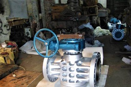
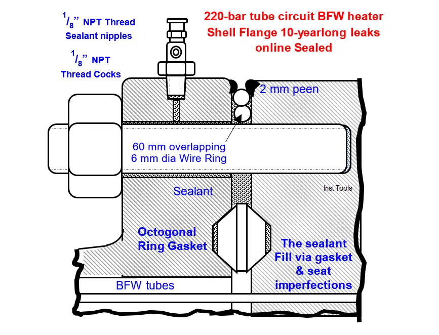
The Fig 1 shows 28 Nos. 2½” studs securing the boiler feed water heater (BFWH) 1283 mm OD x 83 thick shell flange to the channel head. The factory has expanded, and seal welded the 400 Nos.
U-tubes’ 800 ends to the channel head (CH). 275o C 220 bars synthesis enters the CH top chamber, heats the 60‑bars 110o C BFW, returns to the bottom chamber and exits for further processing.
Octagonal ring gasket seals the channel head to shell flange joint (fig 1).
Though, octagonal ring gaskets serve well in hot high-pressure applications in this case it leaked from day 1. Several gasket changes and seat lapping using specially made CI lapping piece did not solve the problem. Hence, the plant had to live with the 10‑yearlong BFW leaks.
The author instrument engineer suggested online sealing as nothing else worked. Everyone including the maintenance manager derisively laughed as if silly, and continued living with the leaks and associated numerous other ill effects.
The author on becoming maintenance manager overruled all objections and attempted online sealing as the cost was pittance Rs 50000. Just leaks reductions alone would pay that amount in few months.
How the online sealing contractor stopped the leaks
Below are the details:
- The huge steam leaks spread flashed BFW steam & condensate mix and around the flange gap up to some distance from there. Vendor Technician 1 (VT1) donning water proof coveralls, hardhat and goggles – to protect himself from the shower – drilled a 3 dia as in fig 1 up to the bolt hole on the 83 mm wide shell flange. He enlarged it 10-mm deep and tapped 1/8” NPT thread. He screwed in 1/8”‑ NPT threaded sealant cock at the hole. He left cock open
- He screwed in 27 more open sealant cocks at the other bolt locations. Such holes drilling negligibly affects the flange strength.
- Since he did this hard task in the rough environment, he took periodic short rest pauses and drank enough water to prevent dehydration. During his rest pause VT2 took over to finish the task soonest. Jobs till now are relatively easy as leaks continued obstruction free.
- VT1 inserted a 6 mm dia non-springy steel wire in the flange gap and held the end 1 pressed against a bolt periphery with a screw driver.
- VT2 circled the wire end 2 over the bolts up to the start point and overlapped it over end 1 60 mm.
- VT2 took over; he peened in the shell flange and channel head edges inwards by around 2-mm by hammering a blunt chisel all around the corner. Tasks 5 & 6 were also relatively easy as the open cocks vented away the leaks.
- Gap pressure increase because of the installed cocks obstructing leak flows partially butted the wire ring (WR) square with the peens which prevented the ring ejection. The wire ends overlap still continued.
- VT 2 closed Cock 1 (C1), screwed in Sealant Injection Fitting (SIF) and opened C1. Likewise, 14 cocks went on open C3, C5, C7 … Leaks from SFs were minimal thanks to their ball check valves. In addition thanks to the other 14 no SF open cocks venting the flange leaks VT2 completed step 8 with increasing difficulty because increasing flange gap pressure despite 14-cocks venting
- VT1 took over. He pumped in the sealant via C1 for 5 minutes, and diametrically opposite cocks for 5 minutes. Thus he pumped in sealant through the 14 cocks for 2 hours at 5 minutes intervals following a flange bolts tightening routine. Thanks to sealant injection total leaks reduced 80% by 8‑PM.
- They departed telling that they are so tired that they would have a quick hot shower, dinner and hit the sack the soonest.
- VT2 closed C2, fitted a SF on it and opened it the next day 8 AM. This way he fitted 10 sealant fittings leaving 4-diametrically opposite cocks open.
- He continued injecting sealant in the 10 SFs following flange bolt tightening pattern for 6-hours
- Gone are the 10-yearlong shell flange leaks
- He screwed in SFs in the remaining cocks and injected sealant through them for ½ hour and closed them, and ensured all closed cocks
- Both enjoyed the plant canteen provided special late lunch, collected the check and departed satisfied with a well completed tough job and quick payment.
VT stuck to our below given instructions
- “Limit Sealant Pressure to 75 Bars i.e. 125% of Shell Design Pressure to avoid excessive stud loads, stud stretches, flange separation and associated excessive more than before leaks
- In addition, we satisfied ourselves the peen’s ability to retain the ring under sealing conditions as below:
- Flange OD (DF) 1283 mm
- Wire dia = flange gap (d) = 6 mm
- Shell Process Pressure (PBFW) = 60 bars
- Max Sealant Pressure 1.25PBFW
- Wire eject force (F) =1.25*10^-2*DF*PBFW*d =1.25*10^-2*1283*60*6 = 5774 kg
- Permissible Sheer Stress fs = 1400 (Kg/Cm2)
- Resisting Force F = P()*DF*tpeen*10^2*fs =PI()*1283*(2+2)*10^-2*1400 = 225717kg
- The peen can resist even 40 times the wire ejection force!
Our plant’s ‘Oppose-New-Endeavors Skeptics (ONES) – every plant has few ONES -, objected online sealing vehemently and predicted total failure. The 10-yearlong leak stop stunned, they declared for face saving, “Don’t be too jubilant; leaks will re-appear in few days.”
The online sealed joint leaked negligibly on starting the plant after the 18‑months interval every turnaround (TA). Plant crew’s just ½ hour long sealant injection after the entire plant stabilization stopped the small leaks.
No alternative left, the ONES also grudgingly congratulated the author’s off the beaten path revolutionary, highly successful, economical and effective solution.
Ten yearlong leaks stopping Benefits
- Leaking BFW flash, condensation and drizzle over the structural members vanished
- 20T/H expensive treated BFW and the pre-heat spent losses vanished – enormous recurring money savings
- The leaks drizzle wetting aggravated many times more the already high external corrosion rate from the nearby urea prill-tower fallout.
- Hence, despite sandblast surface cleaning, and expensive paints application during the TAs the structures rusted within months into eyesores. Besides creating maintenance lack impression, structures’ thinning threatened unpredictable collapse accidents. Flashing BFW leaks drizzle prevented during plant runs painting.
- Pipelines, control valves and the structure carried field pressure, temperature transmitters; PSs, TSs, etc. malfunctioned because of the above-described drizzle and corrosion. Consequent spurious alarms, trips and failed real situation alarms and no trips confused the operators, posed serious safety hazards and lowered operators’ morale
- The drizzle made failed instruments, especially those with electrical contacts restoration uphill tasks
- The leak stopping eliminated all the above safety risks and high costs
- Often vainly repeated online E‑702 shell bolts hot bolting and during TA gasket renewals vanished
- The heavy leaks absence enhanced personnel and plant safety and everyone’s morale immensely
- Stopped the factory inspectors’ and visitors’ adverse comments
- Above all the lasting painting prevented structures rusting and prevented their strength loss and eliminated the collapse accident threat worries.
- The structures carried annoying instruments failures also vanished and assured safe plant operation
- Structures, pressure vessels and other plant painting and strength loss prevention met the corporate goal “Keep the plant young”, pleased the top management and production went up by 10%.
This Case Study take outs
This Case Study take outs are:
- Solve plant problems following standard maintenance practices and best engineering practices
- If these fail and the problem persists posing safety hazards, materials wastage, reducing plants life and high costs consider other methods even if other disciplines persons or whoever suggest, after duly satisfying yourself the alternatives safety aspects, success and durability potential and costs.
Author: S. Raghava Chari
Do you face any similar issues? Share with us through the below comments section.
If you liked this article, then please subscribe to our YouTube Channel for Instrumentation, Electrical, PLC, and SCADA video tutorials.
You can also follow us on Facebook and Twitter to receive daily updates.
Read Next:
- Plug Valves Leaks
- Rupture Discs bursts
- Trip Throttle Valve RCA
- Repeat Safety Valve Popping
- Steam Letdown Station Problems