In this article, you will learn the temperature transmitter preventive maintenance procedure and the RTD & thermocouple sensors validation.
Tools
We need the following tools to carry out the maintenance of temperature transmitters.
- Digital Multimeter
- Decade Box for RTD
- Scandura or Beamex for thermocouple as a primary sensing element
- HART communicator
- Tool bag with all necessary tools
The above tools must be calibrated with master instruments and must have their validity to use for our calibration & maintenance activities.
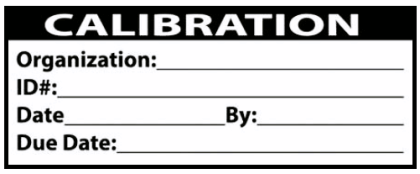
We need calibration stickers. We have to stick the updated labels on the transmitters and other instruments after completing the PM job.
We have to carry all the required personal protective equipment (PPE) for our PM job.
We need the datasheet for the instruments which are to be planned for maintenance. So we need datasheets for the temperature element and transmitter.
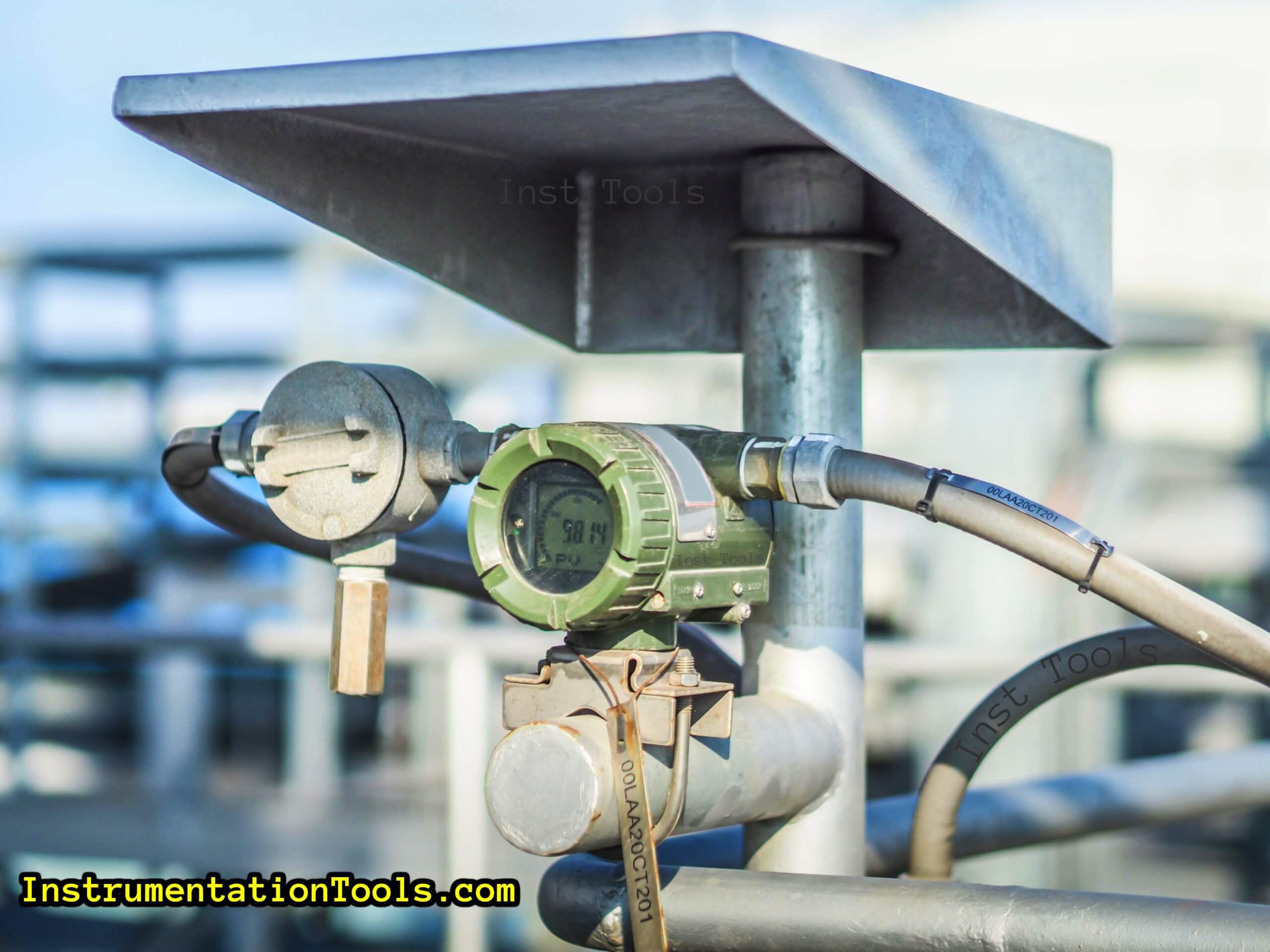
Temperature Transmitter Preventive Maintenance Procedure
- Take appropriate work permits and take necessary approvals.
- Bypass the interlock if the temperature transmitter is having any interlocks (Always take a bypass approval from operations and fill the Interlock Bypass Form).
- If a temperature transmitter is used for process control using a control valve, then ask the operation engineer to put the control valve in manual mode.
- Verify the temperature transmitter tag number. You should always ask the value shown by the temperature transmitter on DCS/SCADA/PLC and confirm the value in the field. This is a double confirmation for identifying the proper tag.
- Note down the present value shown by the temperature transmitter before the PM job.
- Open the back cover of the temperature transmitter and you will find the cable connection terminals.
- Note down all the cable connections. So that after job completion, all cable connections are properly restored back.
- Check the supply voltage.
- Remove the sensor cable connections.
- Connect Decade Resistance Box in case of RTD and Scandura or Beamex in case thermocouple with the temperature transmitter. (in place of sensor cables)
- Connect the HART communicator to the temperature transmitter
- As per the range of the temperature transmitter, configure output in Scandura or Beamex for feeding it to the temperature transmitter. (set resistances in decade resistance box for RTD)
- Now apply input values and note down the output of the transmitter (confirm in field display or in HART communicator as well as on DCS/SCADA/PLC).
| % of Range | Input from TCI | Value on field display or HART 375/475 | Value on DCS/SCADA/PLC |
| 0 | 0 | ||
| 25 | 50 | ||
| 50 | 100 | ||
| 75 | 150 | ||
| 100 | 200 | ||
| 75 | 150 | ||
| 50 | 100 | ||
| 25 | 50 | ||
| 0 | 0 |
( For example, The above table is filled for temperatures from 0 to 200 degrees Centigrade)
RTD and Thermocouple Testing
We use thermowells for the installation of thermocouples and RTDs in the industries. So we can remove the installed RTDs and thermocouples safely for testing purposes.
Now take RTD or thermocouple to the instrument workshop or calibration lab.
First, you have to note down the temperature sensor range from the datasheet.
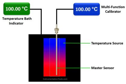
Insert the temperature elements in the temperature bath for validation. Also, insert the reference standard temperature sensor in another slot of the temperature bath.
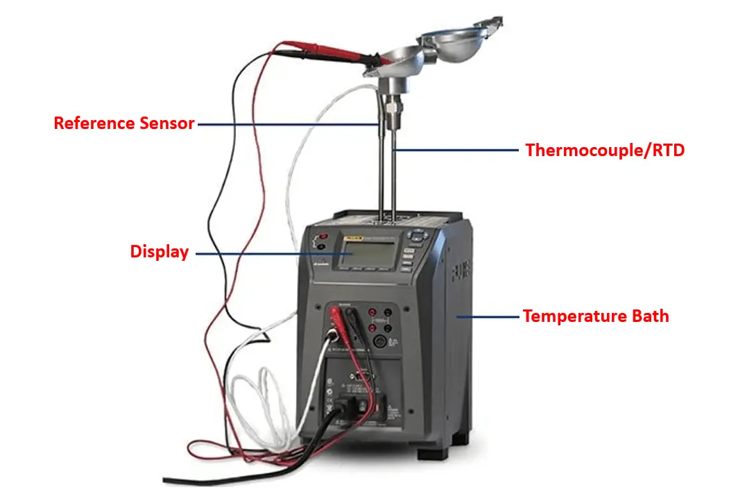
Connect the RTD/thermocouple to temperature baths for measurement purposes, it is available for a few vendor products. (we can also connect them to a multifunction calibrator in order to read the temperature values.)
Set the required temperature on the temperature bath and check the sensor’s output reading. Repeat the same step for different points for the temperature range given in the datasheet.
Use the below-mentioned table to note down the values
| % of Range | Input from temperature bath | Output from RTD or thermocouple |
| 0 | 0 | |
| 25 | 50 | |
| 50 | 100 | |
| 75 | 150 | |
| 100 | 200 | |
| 75 | 150 | |
| 50 | 100 | |
| 25 | 50 | |
| 0 | 0 |
- If both the transmitter and sensor generate the output with an error less than the maximum permissible error, then both are ok. If the transmitter is having error value of more than the maximum permissible error, then calibrate the transmitter. And after calibration, recheck all the values.
- If the temperature sensor is having error value of more than the maximum permissible error, then replace the sensor because it is not possible to calibrate the temperature measuring primary element (RTD and thermocouple). If the sensor does not pass the calibration test then discard it.
- Now take the temperature sensor back to the installation location (field) and install it in the original location. Restore the connections as they were before the start of the PM job.
- Verify the condition of the cable lugs. If found in bad condition, then do the cable relugging.
- Close the back cover of the temperature transmitter and apply monsoon tape or silastic whichever is applicable.
- After connections, crosscheck the present values with the old values taken before the PM job and confirm with the operation engineer that they are valid (Because many times due to ongoing process values may differ). If found not ok, then recheck the connections. (optional step)
- Check the tightness of the thermowell bolts. If loose, then do proper tightening.
- Apply a calibration sticker on the temperature transmitter with the appropriate due date.
- Clean the temperature transmitter.
- Restore the interlocks if any are bypassed and also ask the operation engineer to put the loop again in auto mode if taken in manual mode.
- Close the work permit.
- Fill up the calibration record.
PM checklist
PM checklist to be filled:
- Tag number of Instrument
- Order Number
- Permit Number
- Range of Instrument
- Date of Calibration
- Value before doing Job
- Value after doing Job
- Transmitter Make & Model number
- Test and Calibration Instrument used
- Test Result
- Technicians involved in Job
- Engineers involved in Job
If you liked this article, then please subscribe to our YouTube Channel for Electrical, Electronics, Instrumentation, PLC, and SCADA video tutorials.
You can also follow us on Facebook and Twitter to receive daily updates.
Read Next:
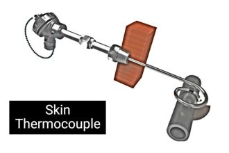
- Skin Type Thermocouple
- Temperature Sensor Failure
- Thermowell Outer Diameter
- Uniformity of Temperature Bath
- Distributed Temperature Sensors