Inst ToolsInst ToolsInst Tools
  • Courses
  • Automation
    • PLC
    • Control System
    • Safety System
    • Communication
    • Fire & Gas System
  • Instrumentation
    • Design
    • Pressure
    • Temperature
    • Flow
    • Level
    • Vibration
    • Analyzer
    • Control Valve
    • Switch
    • Calibration
    • Erection & Commissioning
  • Interview
    • Instrumentation
    • Electrical
    • Electronics
    • Practical
  • Q&A
    • Instrumentation
    • Control System
    • Electrical
    • Electronics
    • Analog Electronics
    • Digital Electronics
    • Power Electronics
    • Microprocessor
  • Request
Search
  • Books
  • Software
  • Projects
  • Process
  • Tools
  • Basics
  • Formula
  • Power Plant
  • Root Cause Analysis
  • Electrical Basics
  • Animation
  • Standards
  • 4-20 mA Course
  • Siemens PLC Course
Reading: Where should we Terminate the Cable Shields ?
Share
Notification Show More
Font ResizerAa
Inst ToolsInst Tools
Font ResizerAa
  • Courses
  • Design
  • PLC
  • Interview
  • Control System
Search
  • Courses
  • Automation
    • PLC
    • Control System
    • Safety System
    • Communication
    • Fire & Gas System
  • Instrumentation
    • Design
    • Pressure
    • Temperature
    • Flow
    • Level
    • Vibration
    • Analyzer
    • Control Valve
    • Switch
    • Calibration
    • Erection & Commissioning
  • Interview
    • Instrumentation
    • Electrical
    • Electronics
    • Practical
  • Q&A
    • Instrumentation
    • Control System
    • Electrical
    • Electronics
    • Analog Electronics
    • Digital Electronics
    • Power Electronics
    • Microprocessor
  • Request
Follow US
All rights reserved. Reproduction in whole or in part without written permission is prohibited.
Inst Tools > Blog > Instrumentation Design > Where should we Terminate the Cable Shields ?

Where should we Terminate the Cable Shields ?

Last updated: October 8, 2017 6:44 am
Editorial Staff
Instrumentation Design
4 Comments
Share
5 Min Read
SHARE

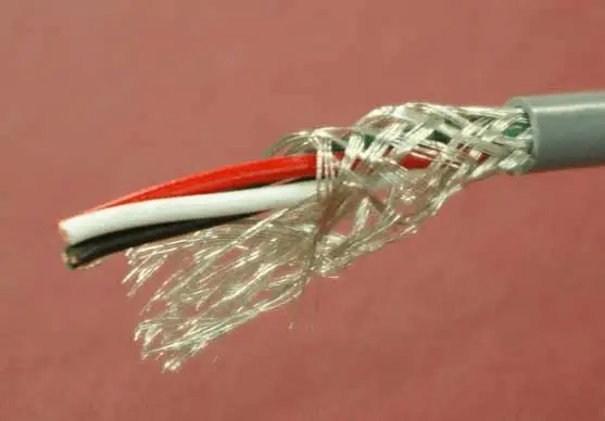
A shielded cable is an electrical cable of one or more insulated conductors enclosed by a common conductive layer. The shield may be composed of braided strands of copper (or other metal, such as aluminium), a non-braided spiral winding of copper tape, or a layer of conducting polymer. Usually this shield is covered with a jacket. The shield acts as a Faraday cage to reduce electrical noise from affecting the signals, and to reduce electromagnetic radiation that may interfere with other devices.

The effectiveness of a cable shield installation depends on the kind of EMI to be shielded and the type of termination at both ends. This paper depicts the different types of cable shielding. Moreover shielding effectiveness is analyzed.

Shielding reduces electrostatic or capacitive coupled electrical noise in signal cable or communications cable

Electrostatic or capacitive coupling is proportional to the capacitance between the noise source and the signal wires. The magnitude of the interference depends on the rate of change of the noise voltage and the capacitance between the noise circuit and the signal circuit.

Where should we terminate the shield and why

Electrostatic noise can be addressed by installing an electrostatic shield (also called a drain) around the signal wires. The currents generated by the noise voltages prefer to flow down the lower impedance path of the shield/drain rather than the signal wires.

The shield/drain must be of a low resistance material such as aluminum or copper. For a loosely braided copper shield (85% braid coverage), the screening factor is about 100 times or 20 dB. For a low resistance multi layered screen, this screening factor can be 35 dB or 3000 times.

The shield should be insulated to prevent inadvertent contact with multiple ground points, which could result in circulating currents.

The shield should never be left floating because that would tend to allow capacitive coupling, rendering the shield useless.

A single point connection to ground attempts to minimize the possibilty of ground-loop current that will flow between grounds at different potentials. A shield grounded at both ends can form a ground loop which can cause a processor to fault if those grounding points are at different potentials.

Vendors may specify grounding the shield at either the field end or the receiver end. When the shield/screen is grounded at one end only, the grounding is usually made in equipment panel/cabinet at the end with the power supply or the receiver. The field device end is left ungrounded and the shield/screen insulated.

At sites with equipotential grounding where the grounding is the same potential between grounding points, some vendors (Profibus DP’s RS-485) recommend grounding the shield at both ends.

Cabling that runs through intermediate junction boxes shall have the integrity and continuity of shield connection maintained in the junction box without connecting the shield to a ground in the junction box.

The signal wire shield is never connected to the common side of a logic circuit (this would introduce noise into the logic circuit).

For high frequency RF noise rejection, a capacitor is inserted in series between the shield’s drain wire and the ground connection.

For some communication network cables, the shield connections are unique to the particular cabling system. In some such cases, a dc short to ground is not needed because a low-impedance ac path to ground and a high-impedance dc path to ground are provided internally at each node. Follow the specific instructions in the publication provided for the specific communication network cabling system.

At any shield grounding connection, do not strip the shield back any further than necessary to make a connection.

Don't Miss Our Updates
Be the first to get exclusive content straight to your email.
We promise not to spam you. You can unsubscribe at any time.
Invalid email address
You've successfully subscribed !

Continue Reading

Troubleshooting a Power Supply Circuit
Electrical Signal and Control Wiring
How to Select a Rotameter? – Parameters and Applications
Instrumentation and Control (I&C) Design
Top 10 Facts about HART Technology
Instruments Tapping Points – Common versus Individual
Share This Article
Facebook Whatsapp Whatsapp LinkedIn Copy Link
Share
4 Comments
  • Rubén says:
    February 12, 2017 at 7:12 pm

    Hola, podrías armar algo con simbología para instrumentación. Gracias

    Spanish to English Translated : Hi, could you put something with symbology for instrumentation. Thank you

    Reply
  • Viral says:
    May 9, 2017 at 2:15 am

    Sir why not connect shield cable transmitter side what is the reason

    Reply
    • azetou says:
      May 9, 2017 at 7:01 am

      Hi, it is mentioned in the article, you ground the shield at one point, either transmitter side or panel/JB side, by doing so you prevent the possibility of formation of ground loops ( circulating undesirable currents) but still you keep draining any currents to the ground.

      Reply
  • Martin! says:
    February 20, 2018 at 9:49 am

    Hi is there any standard that guide to shielding technique. i have to include it in a manual and would like to have a reference. anything ISA IEEE or other know standard un north america??

    Reply

Leave a Reply Cancel reply

Your email address will not be published. Required fields are marked *

Stay Connected

128.3kFollowersLike
69.1kFollowersFollow
210kSubscribersSubscribe
38kFollowersFollow

Categories

Explore More

Pneumatic Valves and Cylinders Sizing – Part 1
Heat Tracing Problems
History of 3-15 psi, 10-50 mA, and 4-20 mA signals
Vendor Document for Project Systems Architecture
Instrument Cables Sheath Material
What is SAMA Diagram?
Air Consumption Calculation for ON/OFF Valves
Blast Furnace Panel Modification to Reduce Down Time by 60 to 70%

Keep Learning

Instrument Protection Methods: Seals

Thermowell Installation near Critical Equipment

Thermowell Installation near Critical Equipment

Magnetic Flow Meter Corrosion Effects

Magnetic Flow Meter Corrosion Effects

Instrumentation and Control Project Packages

Instrumentation and Control Project Packages – Detail Engineering

Field Instruments

Is Vacuum affects Field Instruments in Industries?

Twisted Pair Cable Noise Supression

Why We use Shielded Cable and Twisted Pair Cables ?

Testing of Pneumatic Systems

Testing of Pneumatic Systems

Instrumentation and Control Engineer Subject

Competency Factors of Instrument & Control Engineer (Design Engineering)

Learn More

Auto Sugar Bag Filling Station

Auto Sugar Bag Filling Station

Volumetric Flow Calculations

Volumetric Flow Calculations

Structured Text in PLC: Parking Information Systems

Structured Text in PLC: Parking Information Systems

Steam Turbine Interlocks

What are the Interlocks for Steam Turbine?

Wireless Electric Vehicle Charging

Wireless Electric Vehicle Charging

Certified Automation Professional (CAP) Exam Questions

Certified Automation Professional (CAP) Exam Questions

Ball Valve Parts

What is Ball Valve ?

Fieldbus Signal Status

FF Signal Status

Menu

  • About
  • Privacy Policy
  • Copyright

Quick Links

  • Learn PLC
  • Helping Hand
  • Part Time Job

YouTube Subscribe

Follow US
All rights reserved. Reproduction in whole or in part without written permission is prohibited.
Welcome Back!

Sign in to your account

Username or Email Address
Password

Lost your password?