PLC Temperature Control: In a vessel there are Three Heaters which are used to control the temperature of the vessel.
PLC Temperature Control Programming
We are using Three Thermostats to measure the temperature at each heater. also another thermostat for safety shutoff in case of malfunction or emergency or to avoid over temperatures.
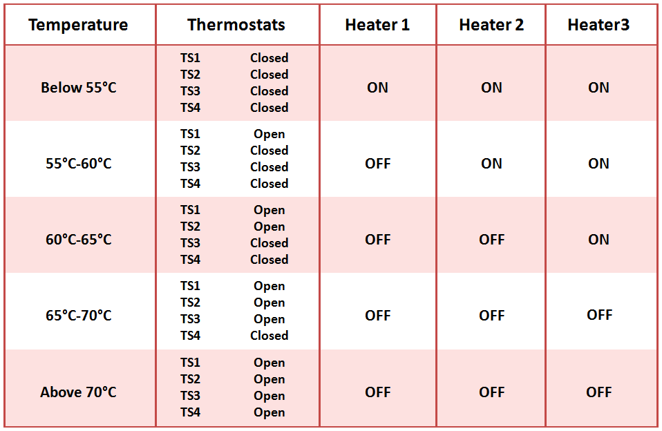
All these heaters have different setpoints or different temperature ranges where heaters can be turned ON accordingly (below table shows the temperature ranges).
- A temperature control system consists of four thermostats. The system operates three heating units. The thermostats (TS1/TS2/TS3/TS4 are set at 55°C, 60°C, 65°C and 70°C.
- Below 55°C temperature, three heaters (H1,H2,H3) are to be in ON state
- Between 55°C – 60°C two heaters (H2,H3) are to be in ON state.
- Between 60°C – 65°C one heater (H3) is to be in ON state.
- Above 70°C all heaters are to be in OFF state, there is a safety shutoff (Relay CR1) in case any heater is operating by mistake.
- A master switch turns the system ON and OFF.
PLC Solution
- There are four thermostats; assume them be in NC state when the set point is not reached.
- Let there be a control relay (CR1) to work as a safety shutoff.
- Master Switch : The Start switch is NO and Stop switch NC type.
The below table shows the temperature ranges where Thermostats (TS1,TS2,TS3,TS4) status will be indicated as per the temperature value.
Also the Heaters (H1,H2,H3) status in which either those Heaters will be ON or OFF as per the temperature value.
PLC Ladder Logic
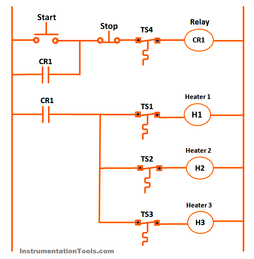
Ladder Logic Operation
First Rung:
It has START button (default NO contact) and STOP button (default NC contact). A Relay CR1 is used to control the heaters depending on the thermostats status.
A Thermostat TS4 is connected in between STOP & Relay, if TS4 activated (means TS4 contact changes from NC to NO) then all heaters will be OFF.
An NO contact of Relay CR1 is used across the START button in order to latch or hold the START command.
Second Rung:
An NO contact of Relay CR1 is used to control the Heaters (H1,H2,H3) with the thermostats (TS1,TS2,TS3) status.
After giving START command, This NO contact becomes NC contact. if temperature below 55 Deg C, TS1, TS2 & TS3 will be in Close Status so all heaters will be ON.
if Temperature is in between 55 to 60 Deg C, Then TS1 will be Open, so Heater H1 will be OFF.
then, if temperature in between 60 to 65 Deg C then TS2 also be Open, so Heater H2 will be OFF
if temperature in between 65 to 70 Deg C then TS3 also be Open, so Heater H3 will be OFF
There is a safety Shutoff which is used to avoid any malfunctions of Thermostats or to avoid over temperatures.
if temperature reaches above 70 Deg C then TS4 will activates and de-energizes the Relay, thus all Heaters will be turned OFF.
Note : Here Heaters H1, H2, H3 are either Relays or Contactors we energizing. so an NO contact of these relays are connected to Electrical Heater feeder circuits (MCC).These Electrical Feeder circuits will be controlled as per these signals and accordingly the heaters will be either ON or OFF.
If you liked this article, then please subscribe to our YouTube Channel for PLC and SCADA video tutorials.
You can also follow us on Facebook and Twitter to receive daily updates.
Read Next:
- PLC Programming languages
- PLC Training Software Download
- Mitsubishi PLC Programming
- PLC Sequence Programming
- RSLogix 5000 PLC Programming





Your program is incomplete : when the temperature goes above 70°C, all heaters will go off, consequently the temperature goes down. if the operator doesn’t press the start button again, all heaters will remain off!!! the process is not fully automated. The program can be improved. Am I right ?
Hi, if we need auto start then we can add (Optional). Ladder logic will be as per our objective which is mentioned in the post. Note : These programs are only for reference purpose or to understand the basic concept. The practical ladder logic will be different, it may include safety related inputs, some interlocks, some machine protection related inputs, also based on our application, requirements etc. Personally, I feel any logic can be improved. There is No End to the upgrades. Its all depends on us. Thanks
Great notes Bharadwaj Reddy
Example logic is wrong
Send me analog program of this circuit
yeah,i need it
hi
i have a question
suppose we have redundant cpu in a plc
one is run and another has stopped
we change damaged cpu with a new one that program is downloaded to it but i/o of this cpu is reseted
if we put this cpu instead of damaged cpu
i/o signal should be read from run cpu
is it ok?
can reseted i/o on new cpu be a problem and set i/o to zero?