Inst ToolsInst ToolsInst Tools
  • Courses
  • Automation
    • PLC
    • Control System
    • Safety System
    • Communication
    • Fire & Gas System
  • Instrumentation
    • Design
    • Pressure
    • Temperature
    • Flow
    • Level
    • Vibration
    • Analyzer
    • Control Valve
    • Switch
    • Calibration
    • Erection & Commissioning
  • Interview
    • Instrumentation
    • Electrical
    • Electronics
    • Practical
  • Q&A
    • Instrumentation
    • Control System
    • Electrical
    • Electronics
    • Analog Electronics
    • Digital Electronics
    • Power Electronics
    • Microprocessor
  • Request
Search
  • Books
  • Software
  • Projects
  • Process
  • Tools
  • Basics
  • Formula
  • Power Plant
  • Root Cause Analysis
  • Electrical Basics
  • Animation
  • Standards
  • 4-20 mA Course
  • Siemens PLC Course
Reading: How a Transistor Switch Works
Share
Font ResizerAa
Inst ToolsInst Tools
Font ResizerAa
  • Courses
  • Design
  • PLC
  • Interview
  • Control System
Search
  • Courses
  • Automation
    • PLC
    • Control System
    • Safety System
    • Communication
    • Fire & Gas System
  • Instrumentation
    • Design
    • Pressure
    • Temperature
    • Flow
    • Level
    • Vibration
    • Analyzer
    • Control Valve
    • Switch
    • Calibration
    • Erection & Commissioning
  • Interview
    • Instrumentation
    • Electrical
    • Electronics
    • Practical
  • Q&A
    • Instrumentation
    • Control System
    • Electrical
    • Electronics
    • Analog Electronics
    • Digital Electronics
    • Power Electronics
    • Microprocessor
  • Request
Follow US
All rights reserved. Reproduction in whole or in part without written permission is prohibited.
Inst Tools > Blog > Animation > How a Transistor Switch Works

How a Transistor Switch Works

Last updated: May 10, 2018 8:36 pm
Editorial Staff
Animation Electronic Basics
3 Comments
Share
1 Min Read
SHARE

Transistor as Switch Working Animation

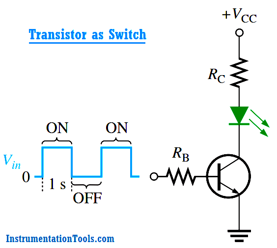
The transistor in Figure is used as a switch to turn the LED on and off. For example, a square wave input voltage with a period of 2 s is applied to the input as indicated. When the square wave is at 0 V, the transistor is in cutoff; and since there is no collector current, the LED does not emit light. When the square wave goes to its high level, the transistor saturates. This forward-biases the LED, and the resulting collector current through the LED causes it to emit light. Thus, the LED is on for 1 second and off for 1 second.

Transistor as Switch Principle


Don't Miss Our Updates
Be the first to get exclusive content straight to your email.
We promise not to spam you. You can unsubscribe at any time.
Invalid email address
You've successfully subscribed !

Continue Reading

Solenoid Valves Types, Principle & Animation
Zener Diode Voltage Regulators
Difference Between Clamp Meters and Multimeters
Resistor Color Code Animation
PLC Sinking and Sourcing Explanation
How to Measure Pressure in Inches of Water Column
Share This Article
Facebook Whatsapp Whatsapp LinkedIn Copy Link
Share
3 Comments
  • zafati mohammed says:
    December 4, 2016 at 5:39 am

    hello
    do you have any ressources to show how to select resistor and transistors for this kind of application
    thanks

    regards

    Reply
  • Ahmed says:
    June 4, 2018 at 11:18 pm

    Direction of currents uncorrect

    Reply
  • kinda says:
    April 27, 2024 at 12:22 am

    useless aplication, u could show how u can make weak source turn on tranzistor to allow more powerful source to flow

    Reply

Leave a Reply Cancel reply

Your email address will not be published. Required fields are marked *

Stay Connected

128.3kFollowersLike
69.1kFollowersFollow
210kSubscribersSubscribe
38kFollowersFollow

Categories

Explore More

Open Loop and Closed Loop Animation
Rotary Level Switch Working principle Animation
Working Principle of Pressure Gauge
Difference Between LDR and Photodiode
How Tilt Level Switch Works ?
Float Type Level Indicator Principle
Hall Effect Sensor Working Principle Animation
Electrical Static Grounding Techniques

Keep Learning

Vibrating Fork Level Switch Working Animation

Vibrating Fork Level Switch Working Animation

Microwave Barrier Level Switch Working Principle

Dead Weight tester

Dead Weight Tester Working Animation

Electrical Wire Mesh

What is an Electrical Wire Mesh?

Ultrasonic Flow meters Working Animation

Ultrasonic Flow Meters Animation

Clamp Meter

Things to Know When Measuring Current

Pressure Transmitter

Pressure Transmitter Animation

load cell in deflection

Load Cell Working Principle

Learn More

Turbine to Gearbox Alignment Drifts Caused Pump Transfers Problems

Turbine to Gearbox Alignment Drifts Caused Pump Transfers Problems

Power Triangle

Power Triangle

Split Range Control Block Diagram

Split Range Control Application using PLC Ladder Logic

Problem in Water Level Control System

Problem in Water Level Control System

Stainless Steel CNC Machined Parts

Everything You Need to Know About Stainless Steel CNC Machined Parts

Typical Switchyard Layout

Electrical Substation – Busbar Arrangements and Layouts

How a Multi Color LED Works

How a Multi Color LED Works ?

Ladder Logic Questions and Answers

Ladder Logic MCQ Questions and Answers

Menu

  • About
  • Privacy Policy
  • Copyright

Quick Links

  • Learn PLC
  • Helping Hand
  • Part Time Job

YouTube Subscribe

Follow US
All rights reserved. Reproduction in whole or in part without written permission is prohibited.
Welcome Back!

Sign in to your account

Username or Email Address
Password

Lost your password?