An essential component of any high-power motor control circuit is some device to detect a condition of excessive overload and interrupt power to the motor before thermal damage occurs. A very simple and common overload protective device is known as an overload heater, consisting of resistive elements connected in series with the three lines of a 3-phase AC motor, designed to heat and to cool at rates modeling the thermal characteristics of the motor itself.
Fuses and circuit breakers also protect against overcurrent, but for different reasons and for different parts of the motor circuit. Both fuses and circuit breakers tend to be fast-acting devices, intended to interrupt overcurrent resulting from an electrical fault such as a phase-to-ground short circuit. They are sized to protect the wiring delivering power to a load, not (necessarily) the load itself. Thermal overload heaters, by contrast, are specifically designed to protect an electric motor from damage resulting from mild overcurrent conditions, such as what might be experienced if the motor becomes mechanically overloaded. The sizing of overload heaters is unrelated to wire ampacity, and therefore unrelated to the ratings of the fuses or circuit breakers delivering line power to the motor.
Also Read : How PLC controls a Motor
A schematic diagram of a three-phase overload connected to a three-phase contactor and three phase motor is shown here:
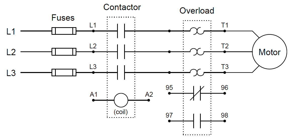
Both contacts inside the overload assembly will remain in their resting (“normal”) states so long as the heater elements (the back-to-back “hook” symbols seen in the above diagram) remain cool. If one or more of the resistive heaters becomes too warm, however, the contacts will actuate and change state. The normally-closed overload contact (terminals 95 and 96) is typically wired in series with the contactor coil (terminals A1 and A2), so that a detected overload condition forces the contactor to de-energize and interrupt power to the motor.
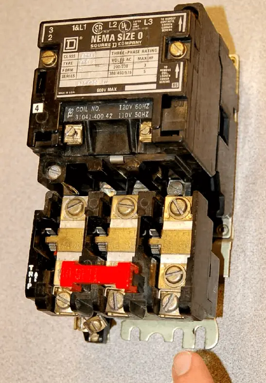
The following photograph shows a three-phase contactor relay joined together with a set of three “overload heaters” through which all of the motor’s current flows. The overload heaters appear as three brass-colored metal strips near a red push-bar labeled “Reset”. The entire assembly – contactor plus overload heaters – is referred to as a starter :
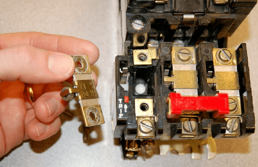
Removing one of the heater elements reveals its mechanical nature: a small toothed wheel on one side engages with a lever when it is bolted into place in the overload assembly. That lever connects to a spring-loaded mechanism charged by the manual actuation of the red “Reset” push-bar, which in turn actuates a small set of electrical switch contacts:
The purpose of the overload heater is to heat up as the motor draws excessive current. The small toothed wheel is held in place by a rod immersed in a solidified mass of solder, encased in a brass cylinder underneath the heater strip. The next photograph shows the underside of the heater element, with the toothed wheel and brass cylinder plainly visible:
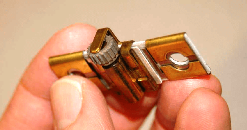
If the heater element becomes too hot (due to excessive motor current), the solder inside the brass cylinder will melt, allowing the toothed wheel to spin. This will release spring tension in the overload mechanism, allowing the small electrical switch to spring to an open state. This “overload contact” then interrupts current to the contactor’s electromagnet coil, causing the contactor to de-energize and the motor to stop.
Manually pressing the “Reset” push-bar will re-set the spring mechanism and re-close the overload contact, allowing the contactor to energize once more, but only once the overload heater element has cooled down enough for the solder inside the brass cylinder to re-solidify. Thus, this simple mechanism prevents the overloaded motor from being immediately re-started after a thermal overload “trip” event, giving it time to cool down as well.
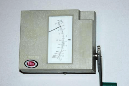
A typical “trip curve” for a thermal overload unit is shown here, with time plotted against the severity of the overcurrent level:
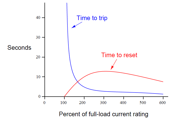
In contrast to a circuit breaker or fuse – which is sized to protect the power wiring from overcurrent heating – the overload heater elements are sized specifically to protect the motor. As such, they act as thermal models of the motor itself, heating to the “trip” point just as fast as the motor itself will heat to the point of maximum rated temperature, and taking just as long to cool to a safe temperature as the motor will. Another difference between overload heaters and breakers/fuses is that the heaters are not designed to directly interrupt current by opening (This is not to say overload heaters cannot fail open, because they can and will under extraordinary circumstances. However, opening like a fuse is not the design function of an overload heater.), as fuses or breakers do. Rather, each overload heater serves the simple purpose of warming proportionately to the magnitude and time duration of motor overcurrent, causing a different electrical contact to open, which in turn triggers the contactor to open and interrupt motor current.
Of course, overload heaters only work to protect the motor from thermal overload if they experience similar ambient temperature conditions. If the motor is situated in a very hot area of the industrial process unit, whereas the overload elements are located in a climate-controlled “motor control center” (MCC) room, they may fail to protect the motor as designed. Conversely, if the overload heaters are located in a hot room while the motor is located in a freezing-cold environment (e.g. the MCC room lacks air conditioning while the motor is located in a freezer), they may “trip” the motor prematurely.
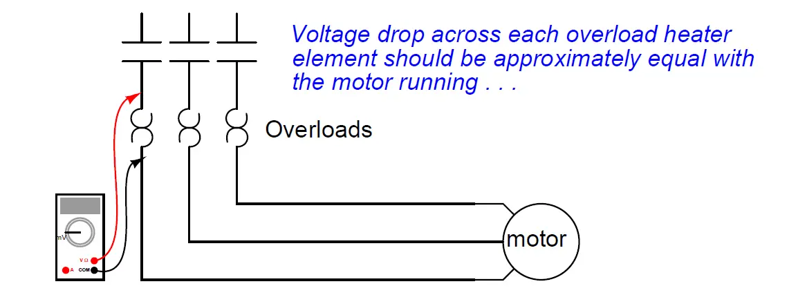
An interesting “trick” to keep in mind for motor control circuit diagnosis is that overload heaters are nothing more than low-value resistors. As such, they will drop small amounts of voltage (usually quite a bit less than 1 volt AC) under full load current. This voltage drop may be used as a simple, qualitative measure of motor phase current. By measuring the voltage dropped across each overload heater (with the motor running), one may ascertain whether or not all phases are carrying equal currents. Of course, overload heaters are not precise enough in their resistance to serve as true current-measuring “shunts,” but they are more than adequate as qualitative indicators of relative phase current, to aid you in determining (for instance) if the motor suffers from an open or high resistance phase winding:
As useful as thermal overload “heaters” are for motor protection, there are more effective technologies available. An alternative way to detect overloading conditions is to monitor the temperature of the stator windings directly, using thermocouples or (more commonly) RTDs, which report winding temperatures to an electronic “trip” unit with the same control responsibilities as an overload heater assembly. This sophisticated approach is used on large (thousands of horsepower) electric motors, and/or in critical process applications where motor reliability is paramount. Machine vibration equipment used to monitor and protect against excessive vibration in rotary machines is often equipped with such temperature-sensing “trip” modules just for this purpose. Not only can motor winding temperatures be monitored, but also bearing temperatures and other temperature sensitive machine components so that the protective function extends beyond the health of the electric motor.
Devices specifically constructed to monitor the condition of electrical power components such as motors, generators, transformers, or distribution lines, and take action to protect those components in the event their parameters fall outside safe limits, are generally known as protective relays. A protective relay is designed to monitor physical variables such as line currents and winding temperatures relevant to a large electrical component, then automatically initiate a “trip” action to shut off power to that component by sending a signal to the nearest circuit breaker or other automatic disconnect device.
Originally, protective relays were electromechanical in nature, using coils, magnets, springs, rotating disks, and other components to detect and act upon out-of-spec electrical measurements. Modern protective relays – for electric motors or for other electric power components such as generators, power lines, and transformers – use microprocessors instead of electromagnetic mechanisms to perform the same basic functions. With microprocessor technology comes vast increases in responsiveness and precision of timing, as well as digital networking capability to share system data among other components and to human operators.
A diagram showing how a modern (digital) protective relay would monitor various parameters on a medium-voltage (4160 volts AC, three-phase) industrial electric motor is shown here:
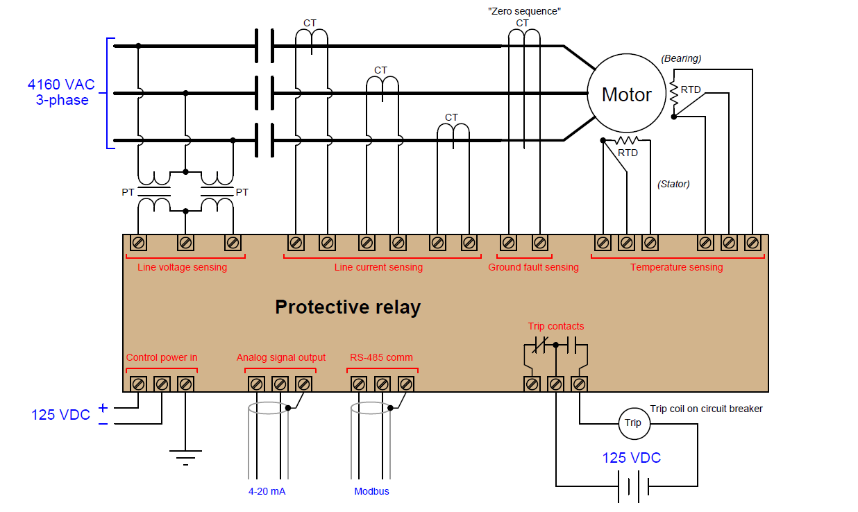
In this example, line voltage (4160 volts AC) and line current are both too great to be directly connected to the protective relay, and so the relay senses line voltage and line current via potential transformers (PTs) and current transformers (CTs), respectively. A potential transformer (Potential transformers are also known as voltage transformers, abbreviated VT.) is a precision device providing a known accurate step-down ratio, usually down to 120 volts or 240 volts AC full-scale, for the protective relay to directly sense. Likewise, a current transformer is a precision device providing a known and accurate step-down ratio for current (actually a stepup from the perspective of voltage), usually down to 1 amp or 5 amps AC full-scale, for the protective relay to directly sense. Both transformers provide galvanic isolation (a complete lack of electrical conductivity) between the medium-voltage motor power conductors and the protective relay electronics while still permitting accurate sensing of line voltage and line current.
The zero sequence CT is a special current transformer encircling all three motor phase conductors, providing indication of a ground fault within the motor. The fact that this CT measures the instantaneous algebraic sum of currents in and out of the motor means that in ordinary operation it will output absolutely zero signal, since Kirchhoff’s Current Law states that the algebraic sum of currents into and out of a node (the motor here is considered a node) must be zero. If, however, a ground fault develops within the motor where some AC current “leaks” from a stator winding to earth ground to return to the 4160 VAC power source’s neutral connection, that imbalance of phase currents will be sensed by the zero sequence CT, since that ground fault current represents a fourth path for current not accounted for by the three power conductors passing through to the motor.
Credits : by Tony R. Kuphaldt – under the terms and conditions of the Creative Commons Attribution 4.0 License