Inst ToolsInst ToolsInst Tools
  • Courses
  • Automation
    • PLC
    • Control System
    • Safety System
    • Communication
    • Fire & Gas System
  • Instrumentation
    • Design
    • Pressure
    • Temperature
    • Flow
    • Level
    • Vibration
    • Analyzer
    • Control Valve
    • Switch
    • Calibration
    • Erection & Commissioning
  • Interview
    • Instrumentation
    • Electrical
    • Electronics
    • Practical
  • Q&A
    • Instrumentation
    • Control System
    • Electrical
    • Electronics
    • Analog Electronics
    • Digital Electronics
    • Power Electronics
    • Microprocessor
  • Request
Search
  • Books
  • Software
  • Projects
  • Process
  • Tools
  • Basics
  • Formula
  • Power Plant
  • Root Cause Analysis
  • Electrical Basics
  • Animation
  • Standards
  • 4-20 mA Course
  • Siemens PLC Course
Reading: How to Select a Inductive Proximity Sensor
Share
Notification Show More
Font ResizerAa
Inst ToolsInst Tools
Font ResizerAa
  • Courses
  • Design
  • PLC
  • Interview
  • Control System
Search
  • Courses
  • Automation
    • PLC
    • Control System
    • Safety System
    • Communication
    • Fire & Gas System
  • Instrumentation
    • Design
    • Pressure
    • Temperature
    • Flow
    • Level
    • Vibration
    • Analyzer
    • Control Valve
    • Switch
    • Calibration
    • Erection & Commissioning
  • Interview
    • Instrumentation
    • Electrical
    • Electronics
    • Practical
  • Q&A
    • Instrumentation
    • Control System
    • Electrical
    • Electronics
    • Analog Electronics
    • Digital Electronics
    • Power Electronics
    • Microprocessor
  • Request
Follow US
All rights reserved. Reproduction in whole or in part without written permission is prohibited.
Inst Tools > Blog > Instrumentation Design > How to Select a Inductive Proximity Sensor

How to Select a Inductive Proximity Sensor

Last updated: February 23, 2016 8:15 am
Editorial Staff
Instrumentation Design
2 Comments
Share
4 Min Read
SHARE

Detecting the presence or absence of a metal may seem like a fairly simple concept, but narrowing your selection to a specific sensor can sometimes be a difficult project. These 6 key attributes can help get you moving in the right direction when it comes to selecting an inductive sensor.

How to Select a Inductive Proximity Sensor

1. Housing design

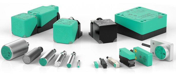
Choosing a housing design is a great place to get the selection process started, as it simply entails looking at the application and deciding what kind of room you have for a sensor. There are many options to choose from, including rectangular/cube sensors, cylindrical sensors, and ring/slot proximity sensors, to name a few. Making sure you select the correct housing style may seem like a simple task, but it is an important decision to ensure your application is handled correctly.

2. Operating distance

Arguably the most important parameter for an inductive proximity sensor is the sensing range. Making sure that you have the correct sensing range can be the difference between sensing a target and missing it altogether. There are a few variations of sensing ranges, but the most straightforward is the nominal sensing range. The nominal sensing range is a standard value for defining the operating distance of a sensor.

3. Mounting conditions

Determining whether your inductive sensor needs to be flush or nonflush mounted is also an important decision. Flush-mounted sensors are great because they can be installed without leaving a space between the mounting surface and sensing face. Another plus for flush-mounted sensors is the fact that they are better protected and less prone to damage than a nonflush mount. But a nonflush mount has its own advantages. One advantage is that they have the greatest sensing range relative to the sensor diameter. For this higher range to be functional, a metal-free space needs to remain around the sensing face so that no incorrect objects are detected.

4. Electric data

Another important criteria is the type and level of supply voltage. An overview of the output circuits for our sensors also be considered. Many manufacturers  product range includes AC, DC, and AC/DC in terms of supply voltage.

5. Connection types

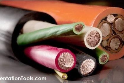
Inductive proximity sensors are available with quick disconnect connection or with a factory-attached cable (pigtail). The quick disconnects enable easy connection, maintenance, and replacement. Cables for the quick disconnect sensors are available in PUR, PVC, POC, and STOOW for your application needs. The factory-attached cables have advantages also. Because the cable is embedded in the sensor, water, oil, or dust cannot penetrate the sensor, making it less susceptible to failure. These cables come in 2 m lengths and are offered with PVC or PUR jackets.

6. General specification and special features

The general specification section of the selection process is an application-specific portion that really depends on any factor not mentioned in one of the first four steps. It can involve the operating or residual current, what degree of protection the sensor needs to be (i.e., IP69K), or if you need a special sensor feature for a special application. Some examples of special-application sensors would be reduction factor 1, weld-immune, and Pile Driver sensors. This section is the last, yet still important, piece to the puzzle of selecting an inductive sensor.

Selecting the most appropriate sensor depends on the application and the material to be detected, and if that material is metal, an inductive sensor is most likely the right choice. These 6 steps should help you select the best inductive sensor for your specific application!

Also Read: How to Select a Pressure Gauge

Don't Miss Our Updates
Be the first to get exclusive content straight to your email.
We promise not to spam you. You can unsubscribe at any time.
Invalid email address
You've successfully subscribed !

Continue Reading

Why Valve Type Matters ? Poppet vs Spool Valves
How to Avoid Process Downtime ?
Cable Routing
Vendor View of Supplying Industrial Process Control & Safety Systems
How to Select a Pneumatic Manifold
Motor Control Circuits
Share This Article
Facebook Whatsapp Whatsapp LinkedIn Copy Link
Share
2 Comments
  • Tarique says:
    November 2, 2018 at 4:45 am

    Very nice working sir..

    Reply
  • Shon Xu says:
    August 30, 2023 at 8:24 am

    This is an absolutely great article for us to choose a right proximity sensor, highly recommended to an engineer or eletrician and thank you Inst Tools teams effort and time to write this article.

    Reply

Leave a Reply Cancel reply

Your email address will not be published. Required fields are marked *

Stay Connected

128.3kFollowersLike
69.1kFollowersFollow
210kSubscribersSubscribe
38kFollowersFollow

Categories

Explore More

How to Calculate Heat Load in Electrical/Electronic Panel Enclosure
When to use a Diaphragm Seal?
How to Calculate Transmitter Performance and Calibration Frequency?
Guided Wave Radar Level Sensor Pressure and Temperature Effects
Technical Specification for Uninterrupted Power Supply (UPS) System
Instrumentation Bulk Material Requirements in Oxygen Service
Level Instruments Design Rules
Types of Cables, Purpose, Advantages, Disadvantages, Applications

Keep Learning

Power Supply Unit with Diode Protection

Why we use Diode Protection Modules ?

Basics of Cable Shields

Basics of Cable Shields

What is FAT and SAT?

What is FAT and SAT? Difference between them

Tagging Philosophy for Junction Box

Tagging Philosophy for Junction Box, Cable, and Cable Drum

IS Loop Formula

Difference between Intrinsic Safe and Non-Intrinsic Safe Cables

Level Instruments

Level Instruments General Specifications

How to Select Right Thermocouple and Thermowell

How to Select Right Thermocouple & Thermowell ?

Air Cylinder Consumption Calculation for Control Valves

Air Cylinder Consumption Calculation for Control Valves

Learn More

Marking Machine

PLC SCL Program for Marking Machine

Calculate LRV and URV for 4-20 mA Loop-powered DP Transmitter

Calculate LRV and URV for 4-20 mA Loop-powered DP Transmitter

HMI configuration for Delta VFD

Modbus Communication between Delta PLC with VFD

Pressure Drop Calculator

Pressure Drop Calculator

Ammonia Gas Detector Calibration

Ammonia Gas Detector Working Principle and Calibration

Calibration Sheet

Calibration : Up-tests and Down-tests

Voltage Control & Circuit Breakers Interview Questions

Voltage Control & Circuit Breakers Interview Questions

Oval Gear Flow Meter Principle

Oval Gear Flow Meters – Principle, Advantages, Animation

Menu

  • About
  • Privacy Policy
  • Copyright

Quick Links

  • Learn PLC
  • Helping Hand
  • Part Time Job

YouTube Subscribe

Follow US
All rights reserved. Reproduction in whole or in part without written permission is prohibited.
Welcome Back!

Sign in to your account

Username or Email Address
Password

Lost your password?