This article explains how to blink lights in ladder logic with a detailed explanation video for beginners.
Note: The ladder logic example is designed for engineering students to practice PLC programming.
How to Blink Lights?
Problem Statement:
Design a PLC ladder logic for the following application.
We are using one toggle switch to control the blinking of light.
Make a light blink with an interval of 2 seconds.
Practical PLC Learning Videos
Our practical PLC learning videos help you master PLC programming with real-time examples.
Digital Inputs
The required inputs are shown below.
Start button: I0.0
Digital Outputs
The required outputs are shown below.
Light: Q0.0
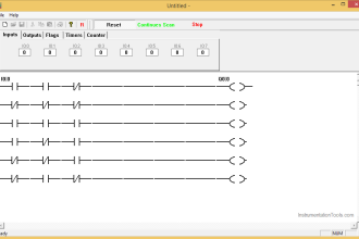
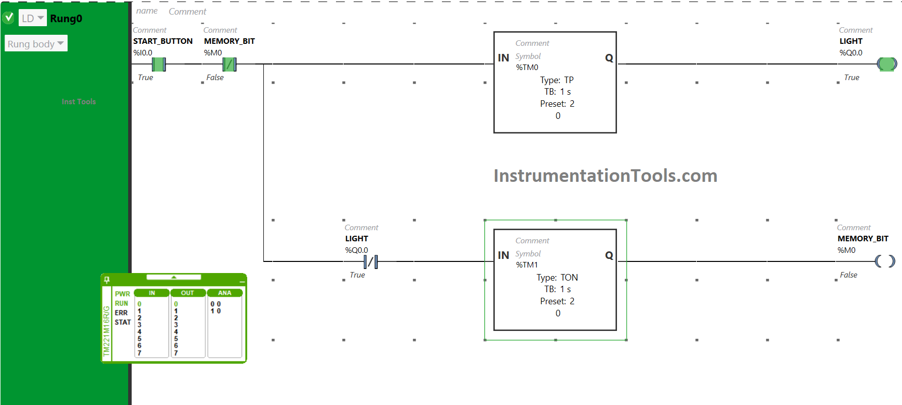
Blink Lights Ladder Logic
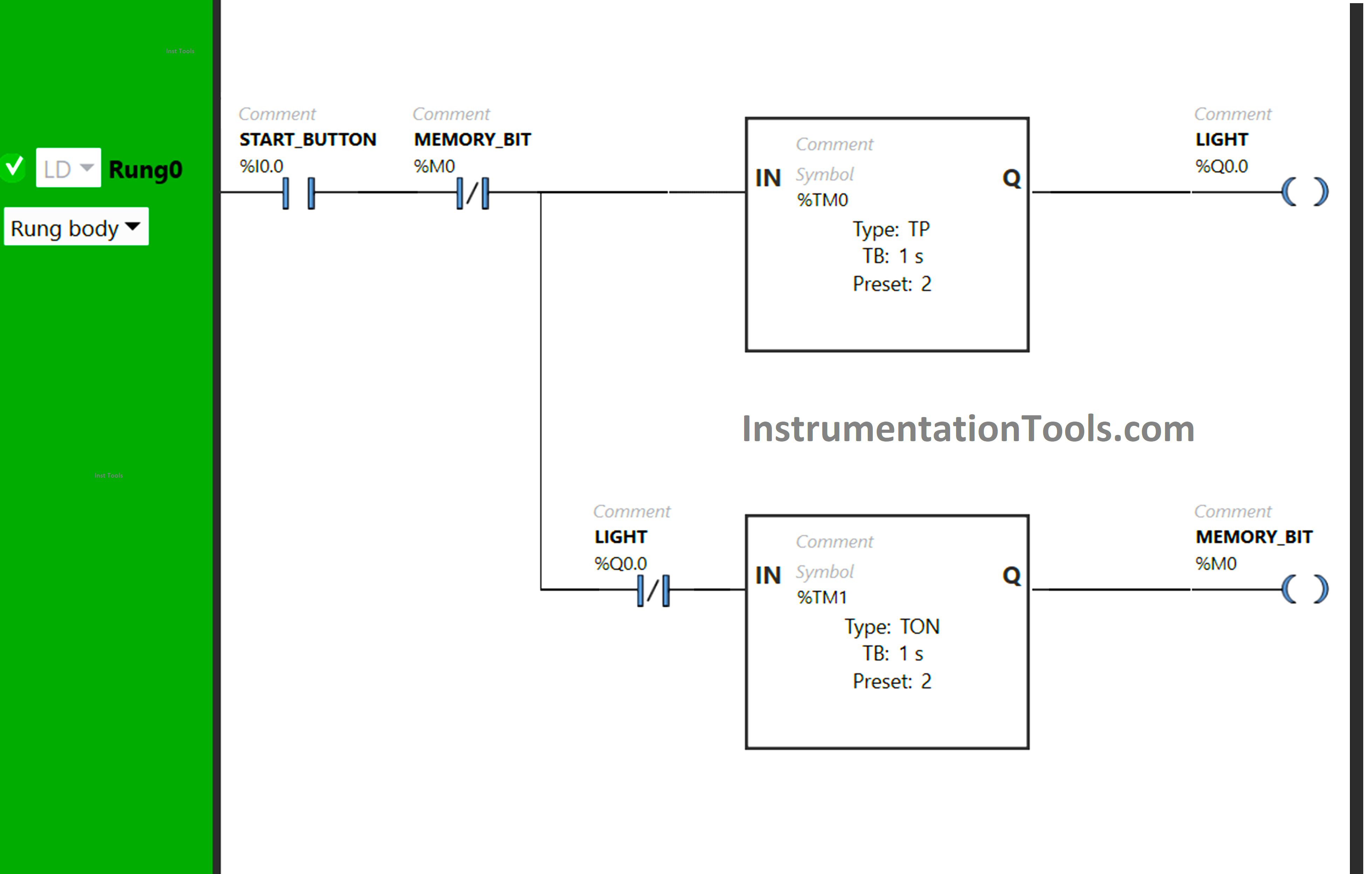
Program Description
We used Normally Open Contact for the Start button.
For Light and memory bit, two Timer Functions Block Type TON and TP are used.
To keep the Light ON for 2 seconds, Timer Function Block type TP is used.
Timer Function Block type TON is used for the Memory bit to turn it ON after a delay of 2 seconds.
PLC Program Summary
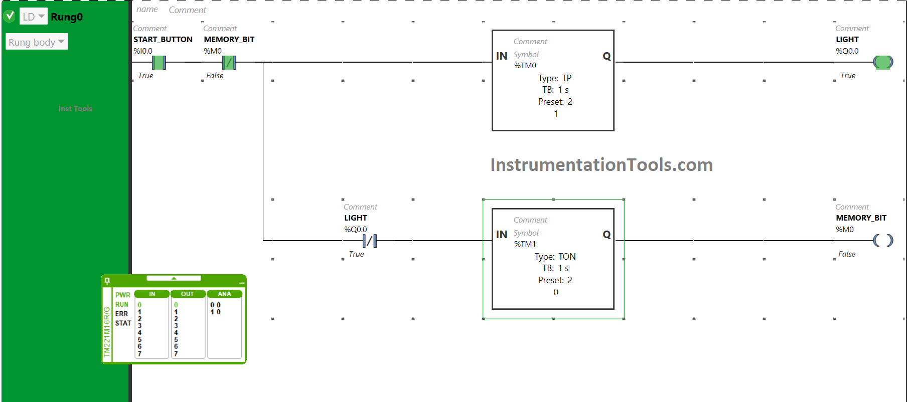
The signal will flow also through the Normally Closed Contact that is used for memory bit as it is false state when the Start button is turned ON.
Timer functional block type TP (TM0) will allow the signal to flow for 2 seconds only. As a result, the Light will be turned ON.
After 2 seconds, the signal will not flow because of the Timer functional block type TP (TM0). The light will turn OFF after being ON for 2 seconds.
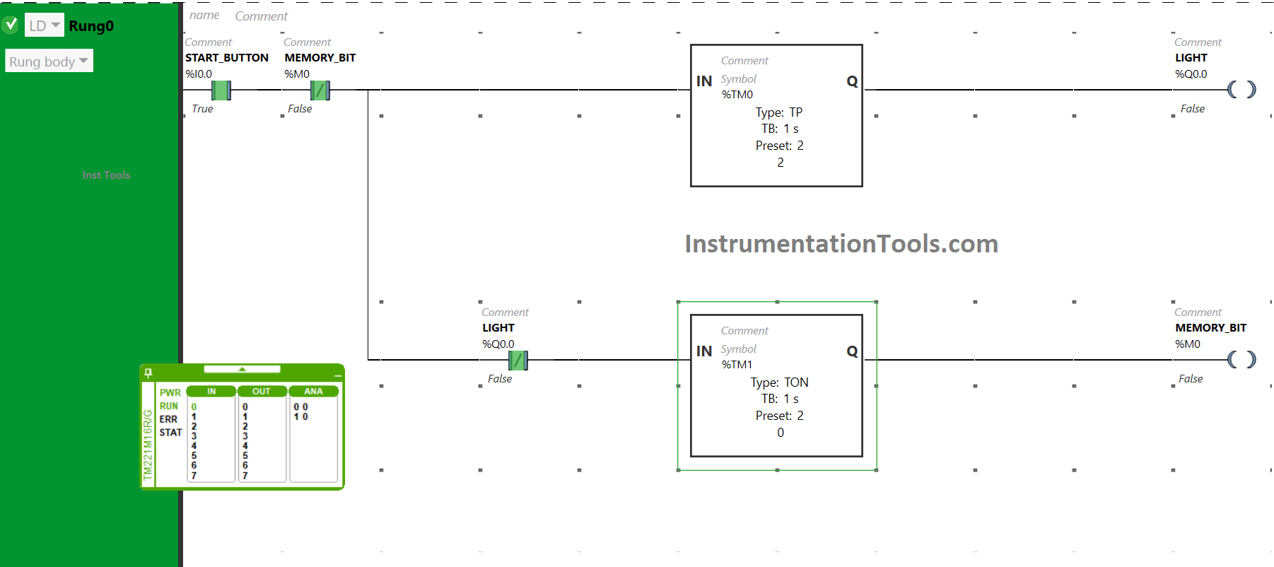
Simultaneously, when the Start button is turned ON and when the Light gets turned OFF after being ON for 1 s, the signal will flow through the Normally Closed contact used for Light. There will be a delay of 2 seconds and after that memory bit gets true.
In those 2 s, the Light will remain OFF. After a delay of 2 seconds, the coil used for the memory bit becomes true, and the Normally Closed Contact used for the Memory Bit will also become true. The Normally Closed Contact in its true state will break the circuit.
As a result, the coil used for the coil memory bit becomes false which in turn makes the Normally Closed Contact used for the memory bit false. The signal will again pass to the Light and it will be turned ON for 2 seconds. After that, it will remain OFF for 2 seconds and then it will repeat the process again and again.
If you liked this article, please subscribe to our YouTube Channel for PLC and SCADA video tutorials.
You can also follow us on Facebook and Twitter to receive daily updates.
Read Next:
- PLC Programming Example with Motor
- InTouch Scada using Scripting Tutorials
- PLC Code to Start & Stop Motor and Pump
- Electrical Ladder Diagram Control with Timers
- PLC Important Questions and Answers