Liquid level measurement constitutes an important aspect in many process industries.
Depending upon their operation principles, level indicators can be grouped into a few categories as mentioned below.
- Mechanical level Indicators
- Optical level indicators
- Electrical level indicators
- Radiation type level indicators.
In this post, we will study mechanical level indicators. And its types along with advantages and disadvantages.
Mechanical Level Indicators
Mechanical level indicators are classified as
Gauge Glass
Fig. (a) tank open to the atmosphere, and (b) pressurized tank.
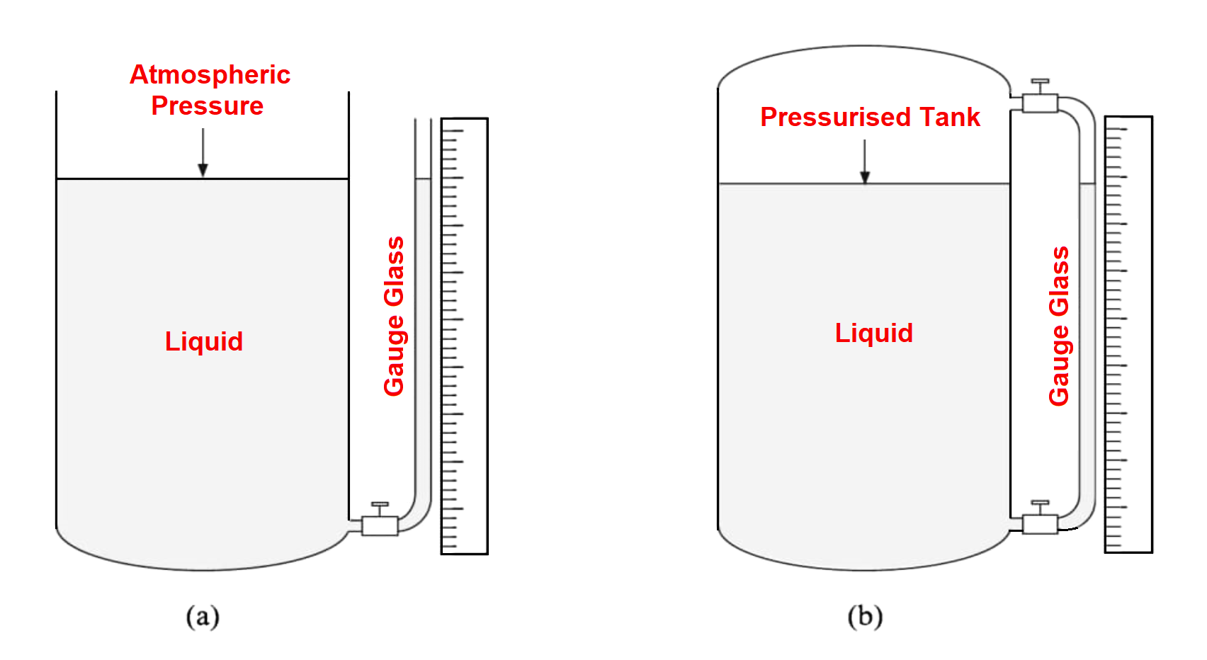
A gauge glass or sight glass is a simple device used to determine the liquid level by fixing a transparent glass tube parallel to the liquid container.
Fig. 1 (a) serves the purpose of level measurement in an open tank arrangement
Fig. 1 (b) serves the purpose of level measurement in closed tank arrangement.
The glass tube should have a small bore and a thick wall so that it can withstand pressure.
To protect it further, it needs to be encased in a metal tube having a slit opening.
Valves are placed at appropriate places for the convenience of replacing broken gauge glass without process disruption.
Generally, Gauge glasses are not used for level heights of more than 90 cm or 3 Feet.
Two or more gauge glasses are required to be fixed at different heights for taller tanks
Generally, glass tubes are selected so that they can withstand a steam pressure of 150 kg/cm², at 250°C. or water pressure of 450 kg/cm².
Bi-Colour Glass Level Gauge
Fig (a) the gauge as it appears, and (b) its working principle
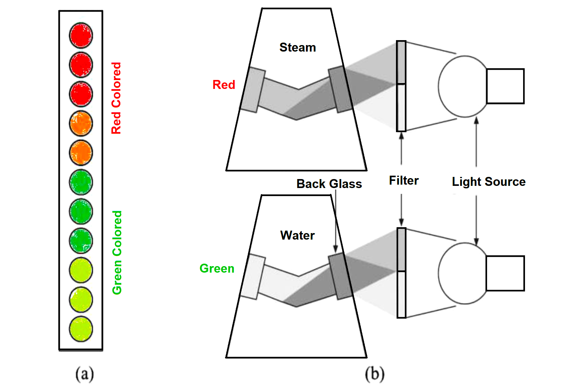
Generally, these Bi-colour glass level gauges are installed in boilers. This Bi-colour glass level gauge shows red color for steam, n and green color for water. This is obtained by exploiting an optical principle of the Refraction Index (RI).
The RI is different for different colors when they pass through media like glass, water, and steam.
The gauge body is a trapezoid with back glasses fixed on the non-parallel faces.
A bi-color light LED lamp or a standard dichroic lamp with red & green filters fixed at the opposite sides on a trapezoid.
This special illumination transmits an oblique light through level gauge back glasses to reach the internal media as shown in Fig. 2b.
When the gauge contains steam, the green rays are deviated & avoided from emerging at the observer’s side. Then red light deviated by steam moves through the internal hole reaching the observer.
Red rays are deviated and lost inside when the ray path contains water so that the green ray reaches the front glass of the level gauge.
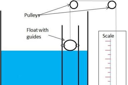
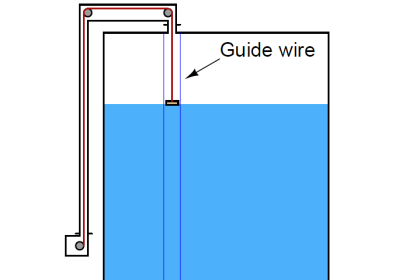
Float Type
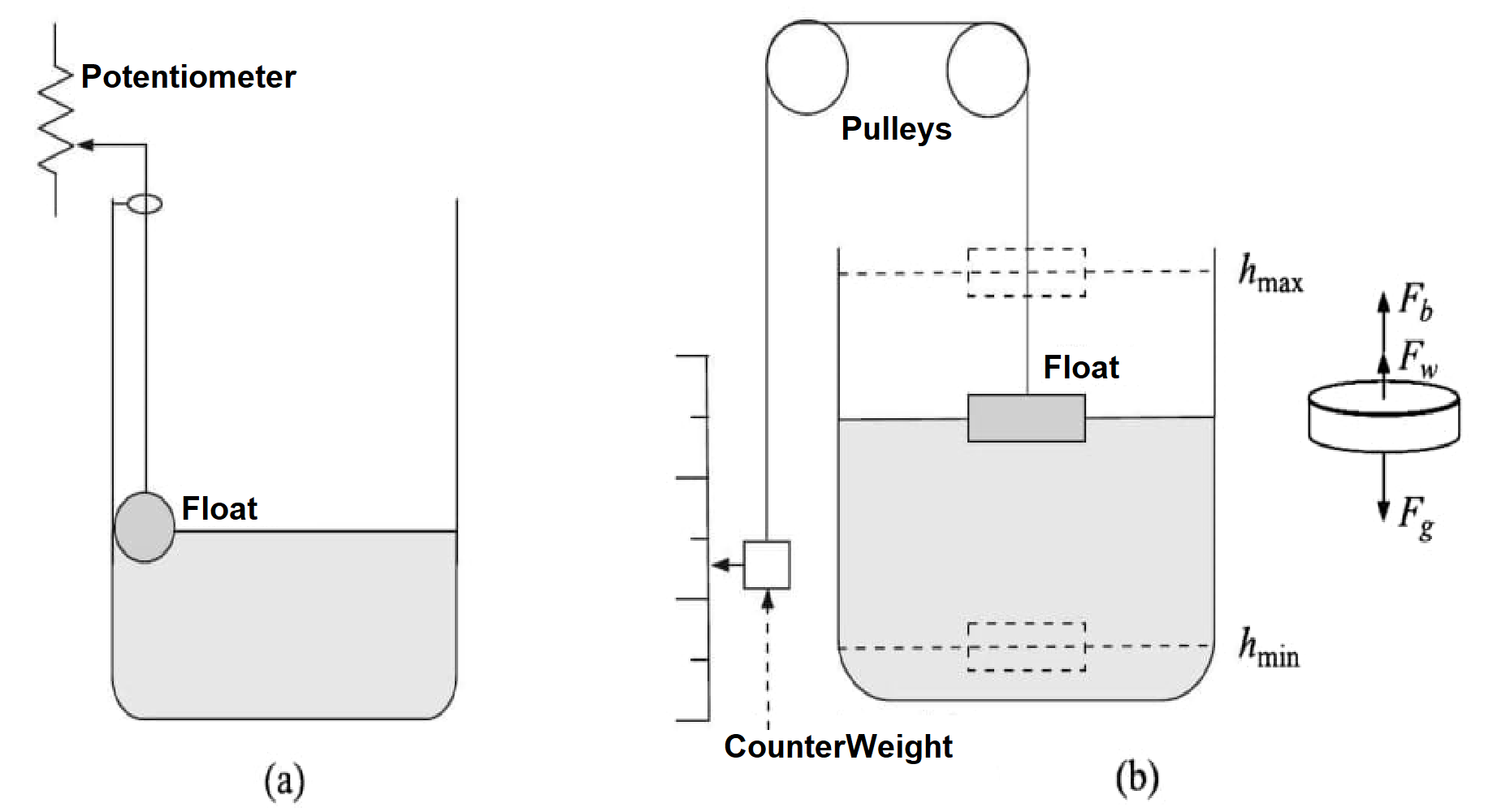
A float is a substance when dipped in a liquid & when floats on the surface of the liquid experience more buoyancy than its actual weight.
According to the principle, the float volume which displaces liquid must be greater than the weight of the float.
Standard Floats
Standard floats are spherical or cylindrical.
The float diameter should be bigger for low-density liquids and vice versa.
The diameter of the Spherical float varies between 75 mm and 175 mm.
Floats may be top-mounted or side-mounted.
Float movement can be tracked electro-mechanically by fixing a potentiometer or LVDT to it.
Magnetically coupled float indicates liquid level as well.
Fig. (a) Potentiometric. (b) Mechanical.
Advantages of Standard floats
- Simple design
- High accuracy
- Wide range of measuring levels
- Possibility of level measurement in corrosive and viscous liquids
Disadvantages of Standard floats
- A standard float cannot be used in tanks under pressure.
Float with Reed Switches
Fig (a) Level indication using reed switches. (b) magnetically-coupled level indicator
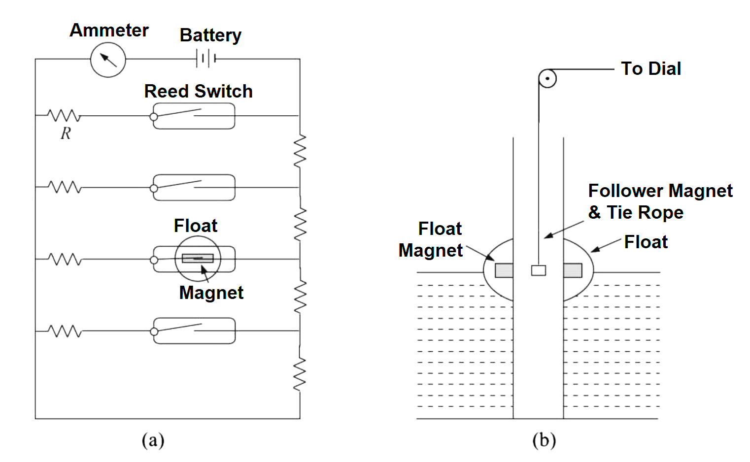
The figure indicates an array of resistors and reed switches connected.
These are generally placed about 5 mm apart in a column.
They float permanent magnet sides along the reed switch column.
The reed switch gets shorted based on the position of the float & sends a current through the ammeter.
The current through the ammeter is more concerning the position of the float
This type of level indicator indicates levels at 5 mm accuracy.
Magnetostrictive Method
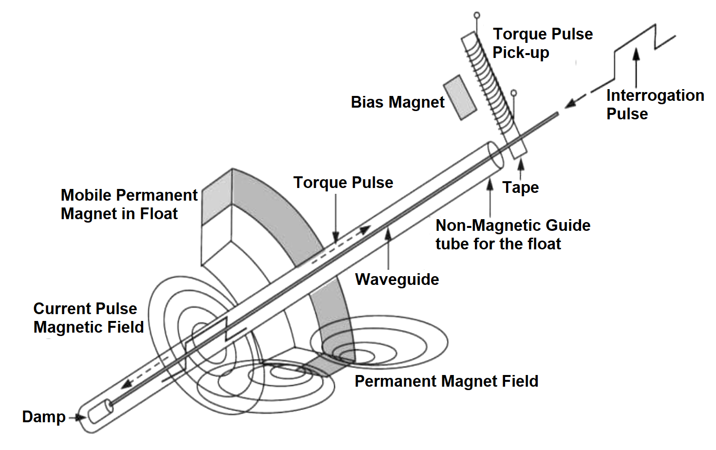
The Magnetostrictive method is the most elegant of all float-level indicators.
The level indication is determining the float position of the liquid.
In the Magnetostrictive method, this float is a concentric circular piece of a permanent magnet.
Wiedemann and Villari’s effects are used to determine the position of the magnetic float on a liquid surface.
Ferromagnetic waveguide material is used to generate magnetostriction.
Generally, a force of attraction between the waveguide and the float magnet raises a frictional force inhibiting the continuous movement of the float.
This can be reduced by using a waveguide of less than 0.5 mm in diameter.
An accuracy of about 0.1 mm can be achieved by this method.
This method is used in pharmaceutical, food, chemical, liquid petroleum gas industries, and beverages.
Displacer Type
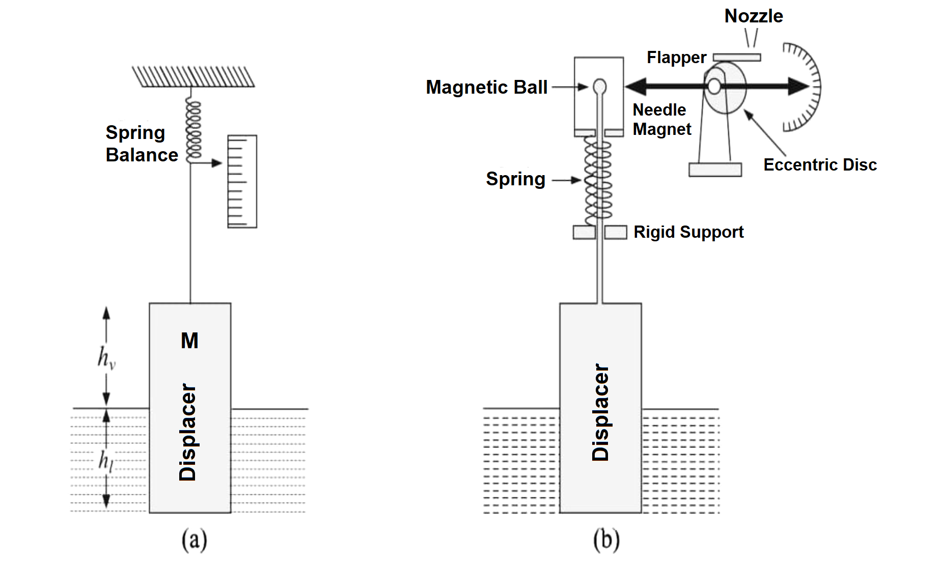
Spring Balance Displacer
This Spring Balance Displacer type considering the origin of the variation of liquid level makes the attached spring contract or expand in upward and downward displacer movement.
The displacer of the rod ends in a magnetic ball.
The magnetic needle fixed on a pivot outside the ball housing senses the up-and-down movement of the magnetic ball.
The movement of the magnetic ball is around 25 mm.
This is magnified pneumatically by attaching the flapper to a disc eccentrically to the pivot of the magnetic needle.
This movement is converted to an electrical signal by a potentiometric arrangement.
Torque Tube Displacer
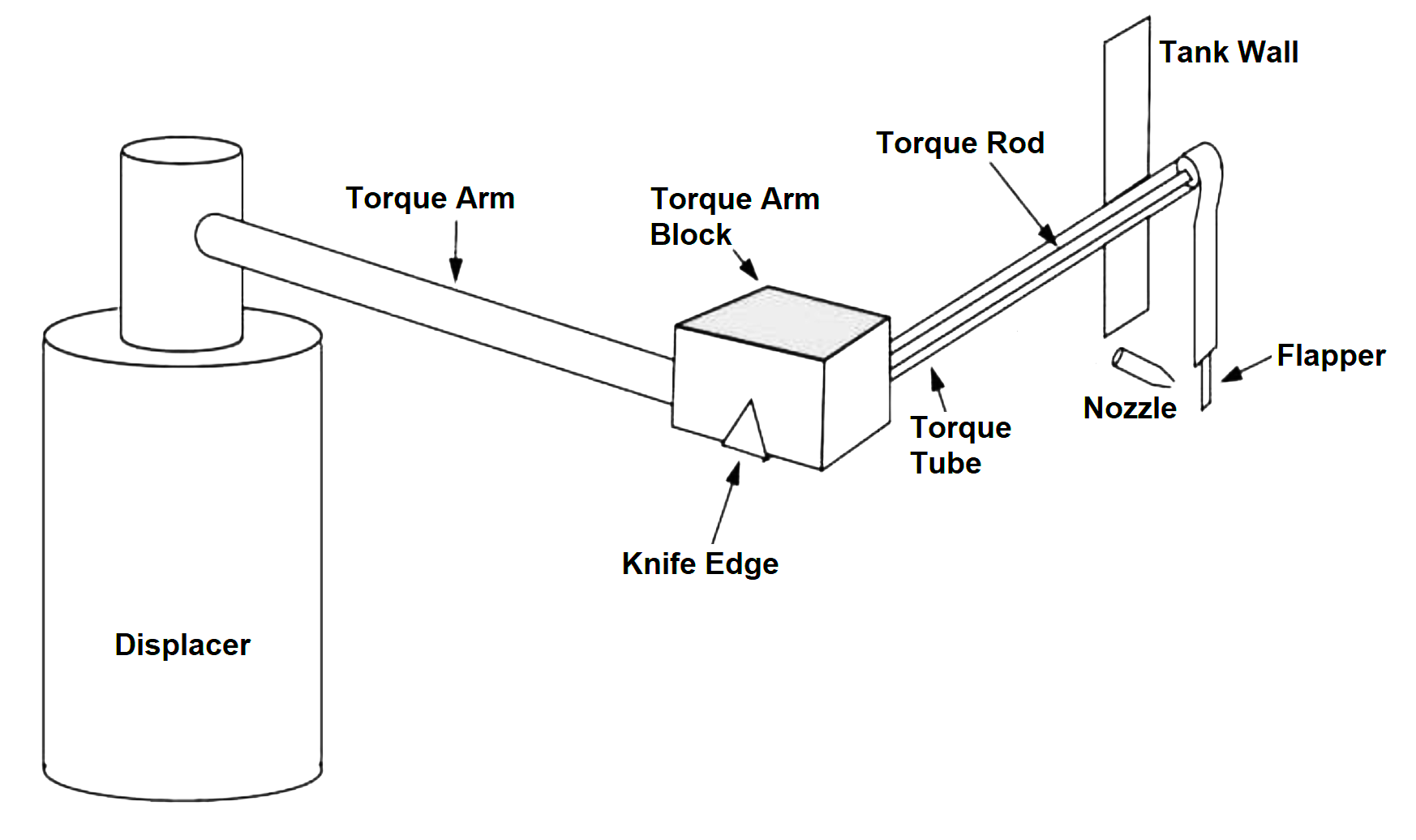
The displacer movement applies torsion to a tube called the torque tube.
The hollow torque tube consists of an inner torque rod welded to the torque tube at one end and free at the other end.
This is supported by a frictionless bearing.
The torque tube ends in a knife edge at one side and supports the displacer via the torque arm which ends in a block.
The other end of the torque tube ends in a flange which is anchored at the tank wall.
When the displacer is moved upward or downward, torsion is applied to the torque tube via its knife edge.
This torsion is transmitted to the inner torsion rod which carries it outside the tank.
The angular displacement of the rod is about 5° to 6°.
The angular displacement of the rod is linearly related to the displacer’s apparent weight & liquid level.
The angular displacement of the torque rod is amplified pneumatically to a large differential pressure by driving the flapper of a nozzle flapper transducer.
Torque tubes are made of Nickel, Inconel, Monel, Hastelloy, etc.
Usually, 0.3m to 1.5 m long displacers are used though the length can be as big as 18m.
Displacers are suitable for level measurement of clean liquids, & Slurries.
To measure the level of a liquid in a tank, a displacer is partially immersed in the liquid as shown in the figure
Figure (a) Displacer Principle (b) Spring-Balance Displacer.
At Equilibrium.
The weight W- δW is measured by the spring balance as
W-δW = Fg-Fb
Where
W ???? weight of the buoy when not dipped in the liquid
δW ???? loss of weight of the buoy when dipped in the liquid
Fg ???? t gravitational force acting downwards on the buoy
Fb ???? is the buoyancy acting
From Archimedes’ Principle
The buoyancy equals the weight of the displaced liquid and vapor by the displacer. So,
Fb = ρlgαhl + ρvgαhv
Where
P and Pu densities of Liquid and Vapour.
hl, & hv, ???? parts of displacer length in the liquid and the vapor above it
g ???? acceleration due to gravity
α ???? area of the cross-section of the displacer
Therefore
W-δW = Mg – (ρlαhl + ρvgαhv)
The resultant force measured by the spring balance, if the displacer is not been dipped in the liquid
W = Mg-ρvgα (h1+ hv)
The loss of displacer weight considering its partial immersion in the liquid
ΔW = gαhl (ρl + ρv)
For the given setup, since, g, α, ρl, ρv are constants
Hence ΔW is directly proportional to hi
Diaphragm Level Indicators
Fig (a) simple, and (b) continuous air-supply type.
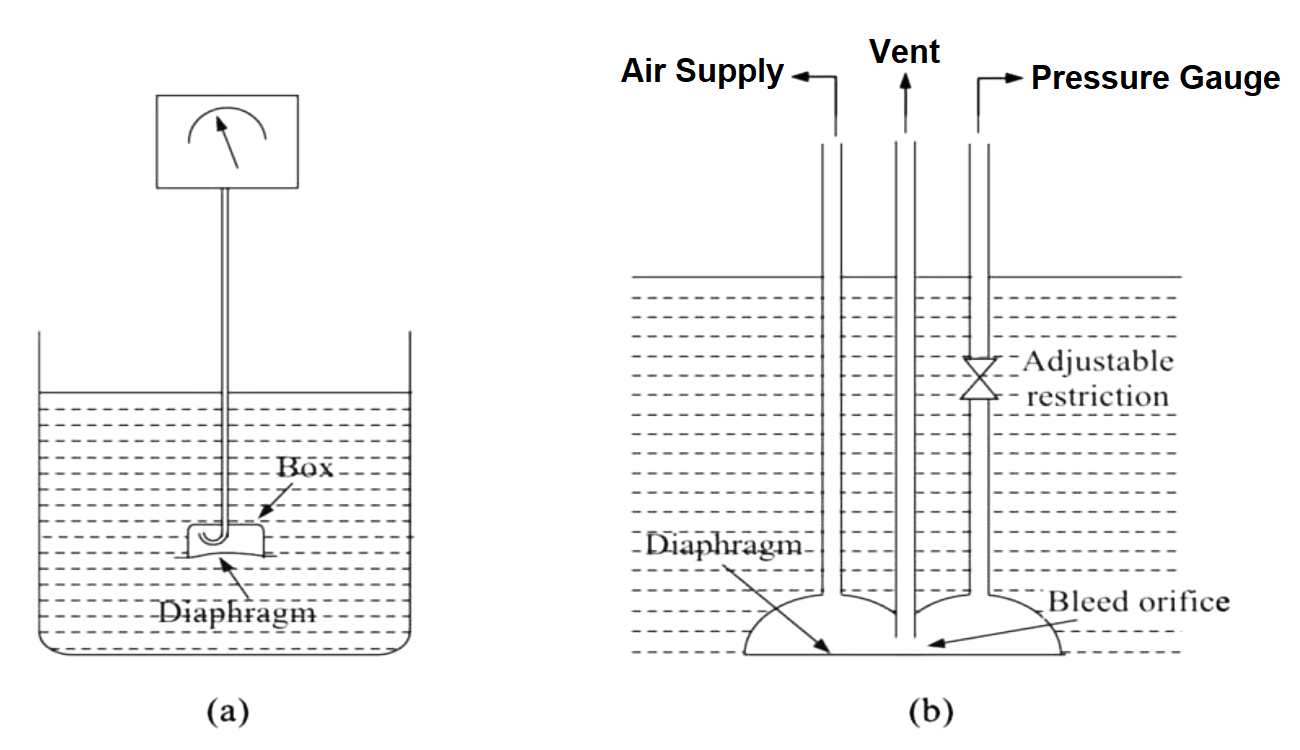
Diaphragm level indicators consist of a box closed on all sides except one where a flexible diaphragm is fixed
The box contains captive air connected to a pressure detector through the capillary tube.
The diaphragm is made of neoprene Teflon or silicone rubber similar plastic material.
The diaphragm box is kept immersed in the liquid.
As the liquid level rises, the static head of the liquid exerts an upward force on the diaphragm to compress the captive air.
The captive air pressure is directly proportional to the liquid level.
This level indicator can be used in open-type vessels.
This is cheaper, with limited accuracy.
The air in the diaphragm is not captive, but a continuous supply is maintained through a tube as shown in figure b.
A vent pipe allows the air to bleed into the atmosphere through a bleed orifice existing between the vent pipe and the diaphragm.
Another pipe connects the diaphragm to a suitable level indicator which is a pressure indicator.
Air supply to the unit is regulated to about 0.2 to 0.3 bars above the maximum hydraulic head to be measured.
Stainless steel diaphragms are suitable for this type of level detector.
As the liquid level rises increased pressure acting on the diaphragm makes it move upward making the bleed orifice smaller.
Consequently, less air leaks through the vent tube causing the air pressure to build up.
The built-up air pressure then pushes the diaphragm down increasing the air leakage and so on till equilibrium is reached.
The air pressure within the diaphragm enclosure is a measure of the liquid level.
These indicators are accurate to within 0.3 bar of the air-supply pressure.
They can operate up to 11 bars.
The adjustable restriction can be suitably manipulated to increase the speed of response.
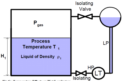
Differential Pressure Level Indicators
Fig. (a) Hydrostatic Tank Gauging, (b) Differential Pressure Level Indicator.
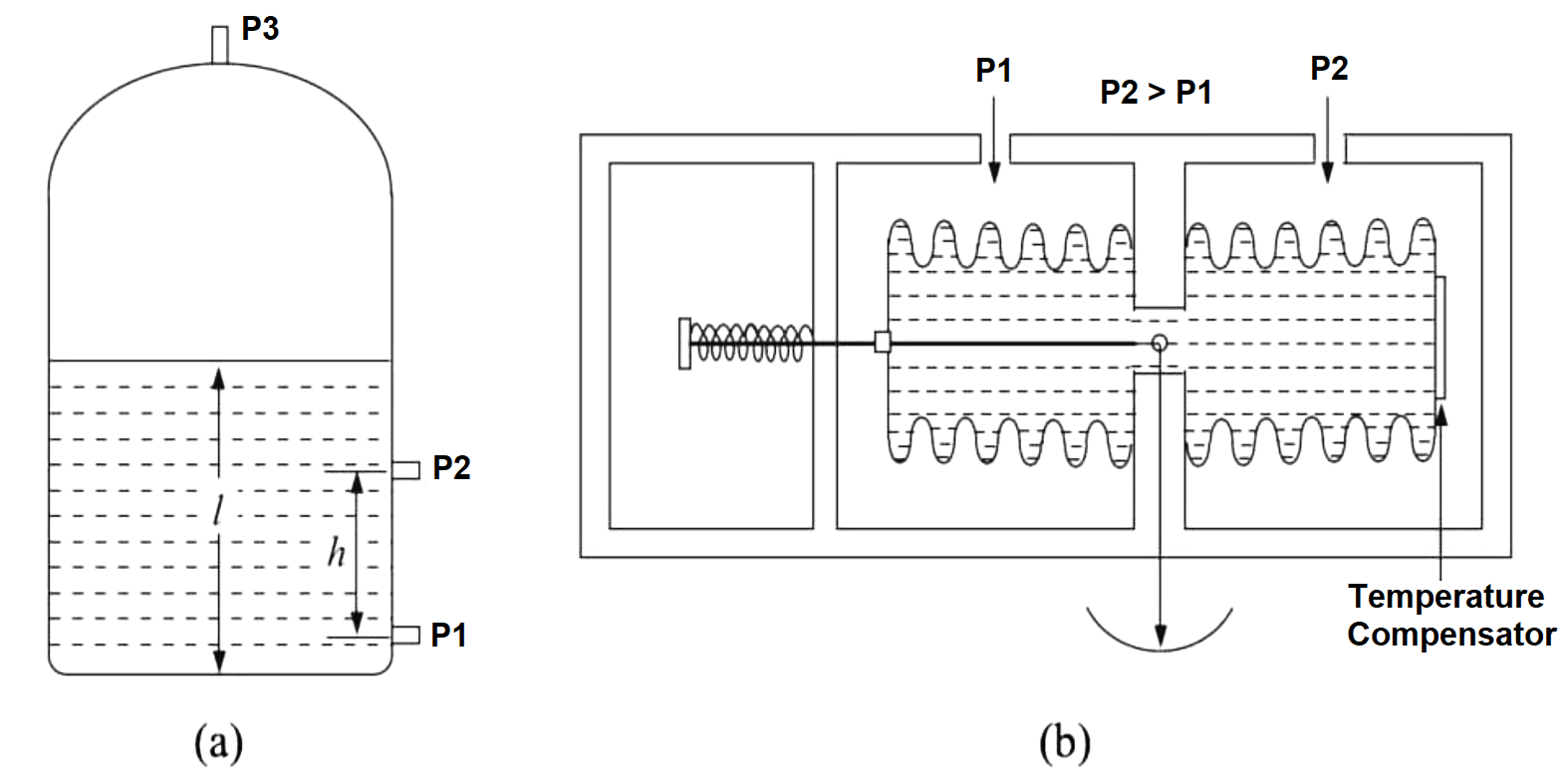
A liquid level exerts pressure caused by the weight of the liquid column.
This pressure can be measured to estimate the liquid level, provided the liquid is at atmospheric pressure.
This method is known as Hydrostatic Tank Gauging (HTG).
But if the liquid is in a pressurized tank, then one needs to measure the differential pressure between the top and bottom of the liquid column to figure out the liquid level.
If P1 is the pressure at the bottom of the tank
P2 is the pressure at an intermediate point
P3 is the pressure at the top of the tank
h is the difference in height between p₁ and p2 tapping points, and
L is the height of the liquid level in the tank
Then ρ = (P1-P2)/hg & L = (P1-P3)/ρg
The pressure difference between the top and bottom of the liquid level can be measured individually by measuring the two pressures.
The measurement error may not be the same.
Therefore, a single measurement gives the differential pressure value.
The DP can be measured mechanically by using bellows in an enclosure where the higher pressure side is connected to the bellows and the lower pressure side is connected to the enclosure.
In this arrangement, as shown in Figure b with liquid-filled bellows used to measure DP, the higher pressure side pushes the liquid inside the bellows to the lower pressure side.
This expands the bellows. As a result, the spring-loaded pointer lever is pushed back, moving the pointer to the right.
Since DP becomes sensitive to the temperature of the liquid.
A bimetallic temperature compensator is attached to the bellows to offset the pressure differential produced by the temperature differential.
If you liked this article, then please subscribe to our YouTube Channel for Instrumentation, Electrical, PLC, and SCADA video tutorials.
You can also follow us on Facebook and Twitter to receive daily updates.
Read Next:
- Skin Type Thermocouple
- Response Time Test of RTD
- Transmitter Burnout Function
- Thermowell Outer Diameter
- Temperature Chamber Calibration